Wow that looks awesome!!
1 Like
This single statement made me feel sooo much better about my sanity at times while messing with equipment in this hobby ![]()
3 Likes
I know right? Chasing a hum is simultaneously one of my favourite and most frustrating things.
2 Likes
Haha right. I cut my power cord a bit ago and it removed all the hum, lights, sounds. It’s so quiet atm.
But seriously, it seems everything can make a difference.
4 Likes
Drives me nuts, even with a scope it’s a pain to track down, and on this particular design because the ground is floating and the only AC ground point is at the input RCA’s, it’s hard to completely isolate the power stage without introducing additional hum.
Headphone amps are definitely “hard mode” when it comes to noise floors.
It’s the thing I’d warn anyone getting into DIY amps about.
It’s not just about putting components together, there is an artform to layout, grounding and running the wires.
4 Likes
I like that. I agree with you. It makes it super interesting and I am still learning how. I’ve been making my own clone pcbs of the Whammy with spare parts to see how it works.
Currently I am trying a layout that splits left and right out from each other to either side of a board, see if that does anything to noise floor.
3 Likes
And another update, I’ve spent the last month+ trying to track down a hum issue only audible with the Utopia. To say this was frustrating would be putting it mildly.
The hum reduces when I tilt the top forwards, and it’s 60Hz, so it’s clearly an RF issue.
I thought the issue was that the top of the case wasn’t grounded because of the anodizing. Fixed that with a Dremel, wasn’t that.
I ran shielded cable every where rational, I tried it without grounding, with the shield grounded to case ground, I tried it with the shield as signal ground.
Re ran AC lines in different locations.
Added decoupling capacitors everywhere power entered the board.
Tried AC grounding the tube heaters.
Nothing seemed to make a difference.
I finally decided it might be the HV supply transformer itself, so I removed it from the case entirely, and lo and behold a significant reduction in hum, so I also removed the Low Voltage toroidal transformer, and no hum.
I tried Building RF barriers inside the case with thin copper sheet, and later with Mu Metal foil, and I just couldn’t get rid of the hum with the transformers inside the case.
So either I needed to move them into a separate box or do this.
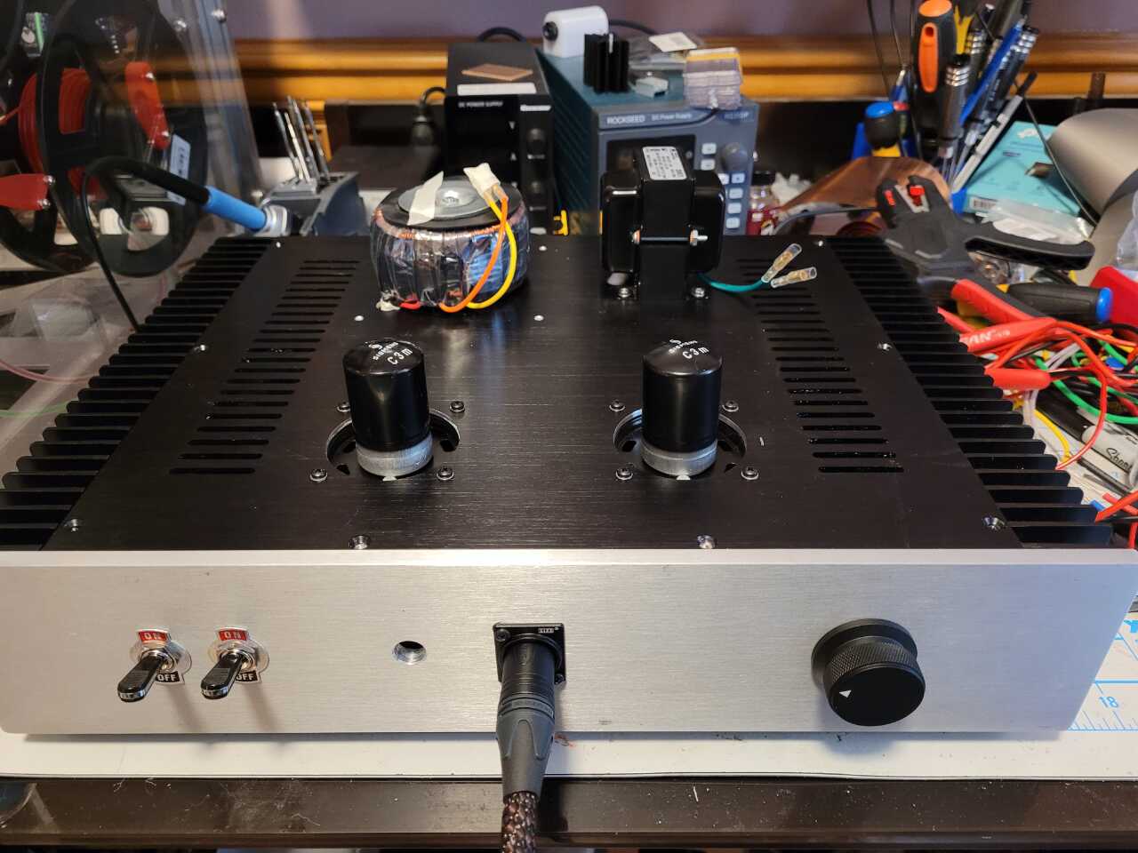
I have a transformer cover coming for the toroidal transformer, and I need to deal with the green wires on the High Voltage Supply.
In retrospect the HV supply being an issue inside the case doesn’t shock me, it’s an EI core transformers, which generate more RF interference than toroid’s, and you commonly see them mounted outside the case in other applications.
Not being able to accommodate the LowVoltage toroidal transformer inside the case was a bit of a surprise.
Just goes to show how important internal layout and probably case size are if you are going to put the transformers inside. Makes solutions like the MSB milled cases a lot more than just eye candy.
10 Likes
Oh well done for tracking it down. Looking forward to seeing the final form. How is it sounding?
2 Likes
Obviously I’m biased, but I’m extremely happy with it, it exceeded my greatest expectations to be honest.
I’m considering replacing the Studio T with it, but I need to spend more time listening.
It’s most reminiscent to me of the character of the AIC, which to me is defined by it’s grip on the upper bass, lower mid range, but it has a lot less color than that amp.
Stage is very open, and it has fantastic separation.
I think the C3M input section is largely responsible the compelling sound. The massively oversized coupling capacitors and Mosfet output section give it the grip in the bass that I think most transformer coupled pure tube amps lack.
I am disappointed I couldn’t make it work as I originally designed it with the headphone output directly coupled. But the DC offset varies too much as the amp comes up to temperature for me to be comfortable with that, I’d need to add a DC servo and significant complexity to remove that, so I’ll live with the output caps.
I still have to add a Mute switch, because there is a loud squeal for about 1 second if you power it on with headphones connected. In an ideal world I’d add a muting relay, but for me I’ll add a switch that selects “gain”, with the middle position as mute.
7 Likes
I was curious about the sound of this architecture. What you say makes sense to me, having the tube for the fine work and mosfets for the power. Adding coupling caps sounds a better solution than something horribly complex. What led to you choosing caps as the coupling?
You should claim the squeal as a design feature, must mean it is a proper amplifier ![]()
It’s a nice build! I think having to put the transformers top mounted will add to the chunky style of the chassis so aesthetically I see that as a plus ![]()
1 Like
That is a hell of a commendation! Congrats on hitting and exceeding your high marks.
It makes you think there is some special design going into things like the Studio amps where transformers are inside yet theyre dead quiet. Did you put the transformers in the chassis for aesthetics, or is there any risk of them interfering with the tubes (if yours werent metal clad) ?
1 Like
It’s one of the options, interstage it’s something of a no brainer, directly coupling just get’s messy, interstage transformers were an option, but the capacitors are just simpler, and because it’s driving a large input impedance for the output stage, the capacitor can be relatively tiny 0.1uF would give excellent bandwidth, so I used 1uF to be sure.
On the output it’s pretty much down to use a dual rail supply and design for 0 offset (which I originally did). Or use a capacitor to remove the DC offset.
There are 2 problems with designing for 0 offset given the circuit I’m using, the first is that the MOSFETs change gain with temperature and as a result that 0 voltage wonders as the amp warms up. The second is less obvious, while the +ve rail in the Source follower has excellent PSRR so any noise on it is attenuated by probably an additional 60dB before it reaches the output, the -Ve rail is basically directly connected to the output, so you get the ripple with no attenuation.
Now the power supply has very little ripple even under load, and I could probably get away with it, but to me it just made more sense to treat -Ve as Ground where there is no ripple to reject.
The downside is the output coupling capacitance has to be Massive, because it forms a high pass filter with the load. I’m using a 6800uF capacitor, so it has to be an electrolytic, I then bypass that with a 5uF thin film capacitor, which will pass most of the audible frequency.
3 Likes
They have separate power supplies, the issue isn’t coupling/output transformers, it’s just the power transformers, they spew 60Hz noise into the case. If you could build a wall from say 3-6mm aluminum, or possibly thinner steel plate it’s almost certainly be fine.
The space/layout in my case doesn’t allow for that.
3 Likes
Not that it is necessarily the same cause but through my too many years in the HVAC trade I came across noisy transformers many times. I usually kept 5-6 replacements on my truck and inevitably I would get one that was noisy, Like REAL noisy. Sometimes it was a mounting issue (loosening one of the feet would cure it) and sometimes it was just a noisy unit that was just that. I always just swapped in another which would be quiet and return the noisy one to the supply house. Good luck with it. The amp looks really great!
5 Likes
One last picture with the transformer covers and hi low gain switch.
Just moved it off my “bench”. So done for now.
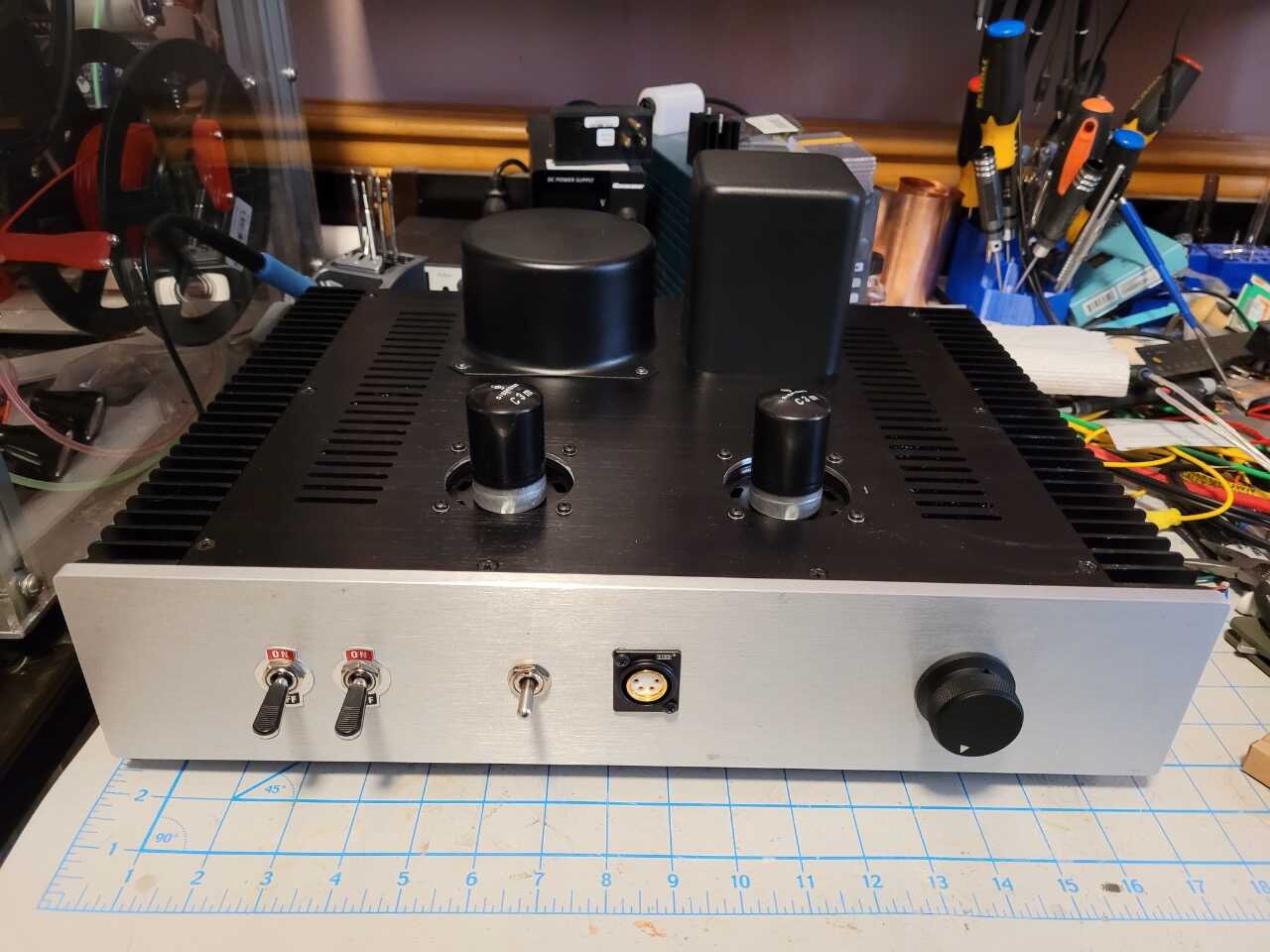
19 Likes
After all those “naked” pictures of the amplifier it’s so very gratifying to see it all dressed up and making it’s way into your listening system soon, it’s been a genuine pleasure and so exciting to follow your progress along the way and it’s also so very exciting to know the hard work paid off in spades ++ as far as performance ![]()
4 Likes
It does look very nice all dressed up. I love the big flipper switches. I really like big, overdone, out of the ordinary switches, knobs, and status indicators.
3 Likes
Yeah I really liked the big flipper switch aesthetic, they are both power switches, left one is the 20V heater/SS supply and the right the 160V for the tube B+.
Even more complicated power on procedure than the Viva, throw the left switch wait for 3x seconds, throw the second power switch wait for a second or 2, then move the mute switch out of it’s center position.
I normally just throw the indicators away, but liked them with the switches.
Unfortunately I couldn’t source the 4PDT switch I use as a low/mute/high switch (guitar amps call these power scalers) with the same style but in the end I kind of like change.
But overall I’m happy with the way it looks.
If I were to build another one, there would be a separate PSU and I’d circuit board mount the tubes, but that has more to do with the pain in the ass it is to assemble with wires running to the top of the case at the front and back, than functionality.
7 Likes
Very much so.
Wire/Trace Routing is 70% of the work, I’d say.
2 Likes