New project - Hybrid Tube/Mosfet Amp

It’s a learning exercise, I’ve learned a great deal about both design and execution building both Amps. I’ll probably revisit the Tube amp at some point and apply some of what I’ve learned about grounding in this build to it.

It’s equal parts fun and frustration, it’s rewarding when it works, but trying to track down what’s causing something is quite maddening on occasion.

Depends what you mean by that.
You very much have to validate the circuit before you can really fine tune components.
This build wasn’t very expensive (the tube amp was), I reused some parts I had on hand and I probably have $300-$400 in parts in it, most of that the transformers and Tubes. The case will cost me another $150 probably. I have some high quality RCA, XLR and Banana Jacks jacks that were $15+ so figure at least $100 for those, the stepped attenuator was $100, I will probably buy a 300V transformer for the tube section, rather than using the 380V one in there now $60.

Moving it to circuit boards probably another $300, though I’ll have spares. I could save money here if I went to a single board, but I want to retain the modularity, I have a couple of alternate output section designs I want to try.

I don’t think I I’ll spend $60 on a resistor (which is what the Audio Note Tantalum Film resistors cost). But when I move this one to circuit boards, I’ll replace the cheap components with Vishay Dale metal film resistors and Nichicon Electrolytics, which will add another $100 to the build probably (mostly in the PSU caps), I’ll splurge on the coupling Caps, and the output caps that will add probably $300.
I might mess around with various other options for resistors and caps afterwards.

There isn’t really any compromise in the design itself.

You can save a lot by finding a workable off the shelf case, and skimping on the PSU by limiting the output power so you can use wall warts, though you’d have to come up with something that will work for the Tube supply, something like the HaggermanTuba design would probably work.

But it’s not a thing you do to save money, though even in it’s current form I feel it sounds better than a lot of multi thousand dollar amps I’ve heard. But I’m biased and I’m the only person to ever hear it :stuck_out_tongue:

4 Likes

I think I mean something where you either refine a current build enough that you swap in some super high end transformers or other parts, or you have a scratch build/concept where the goal is just making everything super high tier. I am sure even then you would need to prototype and have SOME insight in how different trannys will affect the sound (monolith, hashimoto, lundahl) as well as how different power designs and regulators change things

No transformers except in the PSU on this one.
I did want to try an R Core transformer, but it would need to be custom wound, and big enough the weight makes overseas shipping prohibitive.
I have a couple of options for the power supply, including using a reglator, but because it’s a class A amp, it’s not necessary, and really just a different way to control ripple.
My original idea at the top was to use a dual rail supply on the output section, and manually tune out the DC offset to avoid an output capacitor, but after testing I think it will end up with a lower noise floor, using a single rail, though I will still try it both ways.

Part of this build was about being able to try different topologies, capacitor vs transformer coupled, with and without an input transformer, different tubes on the input, different sections, both BJT and Mosfet, feedback vs no feedback, Source followers vs cascode vs ….
Think of it as amplifier Lego. The idea being it’s a lot less work to design and build one piece of an amplifier than the whole thing from scratch. There isn’t even really a compromise for doing that.
How much of that I’ll actually play with I don’t really know.

3 Likes

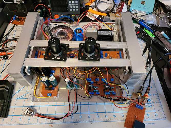
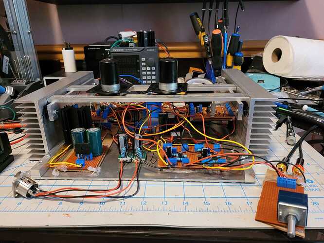
This is a temporary home hence all the hot glue and excessively long tube wiring, there is a backplate I need to finish machining.
Makes it possible to move it, once I have the backplate on so the IEC connector is actually connected to something. It’ll also act as a test mule to test the PCB’s for the final build as they come in.

This version is built as a headphone amp, 1/2 the power supply (about 19V Pk2Pk) current limited to 0.65A that’s 4W and change RMS pure class A into ~14 Ohms (a bit over 3 into 8 Ohms). The Original design was intended to put out 4x that, but it’s adding nothing to a headphone application.

I did run the amp with both half’s of the PSU on the bench which doubles the Voltage/Power, and it sounds much the same, it’s just 2x as much heat to dissipate, I think in the final build I might put a switch in to adjust the drive current, and possibly to enable/disable the second half of the power supply. That way you could have a 16W Speaker amp or a 4W headphone amp that doesn’t get silly hot.

I’ve been listening to it for the last hour or so mostly with the Susvara, and it really is very good, I’d put it in the top 3 amps I’ve heard with the Susvara, and it might not be 3 on that list, though I do need to hear it with a better source.
I think a lot of that is the C3M Pre stage, I can listen to the power stage on it’s own and it’s kind of flat in comparison to with the Pre stage.


9 Likes

Coming along… Nice Heatsinks !

1 Like

The wonders of the internet, There are apparently companies that specialize in heat sink extrusions, I think in this case I ordered from the aptly named heatsinkonline.com.

My original intent was to use wooden front and top plates for the amp, and I might still finish this case that way, but I actually have another complete case for the amp that will arrive in the next few days. Though I won’t transplant it into that until I get PCB’s done.
I just need to review the layouts and how they will be positioned in the final case before I order them.
Just moving it into this case has given me a better idea of how best to ground it.

4 Likes

Always makes sense to have a finished product before case install in case of unforeseen protrusions etc.

2 Likes

Now the best looking amplifier ever!

I ran out of aluminum plate.
The back plate was a tutorial is how not to machine aluminum, but I did manage to rescue it.
I repurposed the top of one of the mono power supplies from the 2A3 Amp as the front plate, hence the additional holes, it’s hot glued to the side rails, so not exactly robust.

I did finally ground it properly at the input jacks, it’s AC grounded through a capacitor to safety ground, and I ran a shielded cable to the front where the volume pot is.

Having said that it means I can carry the amp to another location, and that was the primary goal, and the chance of electric shock is reduced.

Next step is to make some space near the TotalDAC and try it with that as a source.
Going to try and get Circuit boards designed and ordered this week.

7 Likes

Holy crap!! Someone attacked it with a blue Sharpie pen!. LOL! It is coming along nicely.

2 Likes

It’s DNA Blue…

It’s what was the bottom side of the top plate of the PSU, it’s machinist die, you basically scratch it off to mark it. I could remove it, but it was some effort and it’s all temporary.

4 Likes

I knew that LOL but at first glance that is what comes to mind…

2 Likes

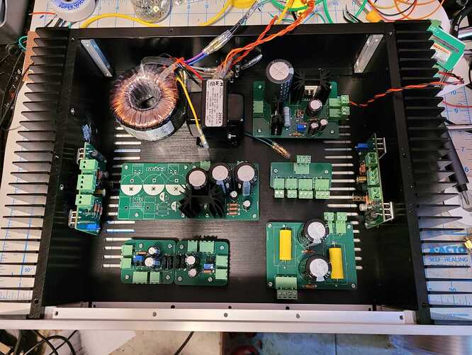
PCBs and final parts came in.
PCB’s were cheaper than I thought they’d be.
They’re all functional, I’d make changes to 2 of them if I were to order them again

I was trying to minimize the footprint of the power boards mounted on the sides, so the screws mounting the MOSFet’s to the heatsinks are completely inaccessible. I actually soldered them in after mounting, though you can get them in and out by bending the legs. In retrospect I’d just flip them around since I have the space.

The pre boards were a pain for two reasons, I screwed up the leg order on the transistors CBE rather than the correct EBC, al that really means is I have to rotate the transistors 180 degrees (though it took me 3 hours to figure out they were wrong), the second is I went with the standard 0.05" lead spacing which is a real pain to solder, I destroyed 3 of them when trying to debug the issue with the board.

Lot’s of holes to mark and drill, not sure I really have the motivation to do it this weekend. I’ll at least get the RCA inputs and Pot mounted though, maybe the power switches and the headphone socket.

If I were making more than one of these I’d probably also just combine everything into a single board or at least the entire power section which is currently 4 boards, and while the flexibility is nice when prototyping

As an aside in testing I noticed the HV transformer was humming… DC offset on your mains I hear you say, but no. One of the screws holding the laminations together was just loose

Test fitting

11 Likes

Still need to mount the tubes to the case and shorten the wires running to them.
But it is all working at this point.

12 Likes

It’s looking cleanly laid out in the chassis. What kind of cables are you going to be using to run the audio signal inside there?

1 Like

It’s all run, the input through the pot into the pre stage is all mogami microphone wire, and the shield is grounded. The rest is twisted pairs of 20 gauge solid core copper. The power wires on the left are 18 gauge stranded copper.
Because the power stage has no gain signals should be large enough it shouldn’t matter much once it exits the pre stage.
The only AC runs down the left side of the case, to the power switches and to the two power supply boards, so there isn’t a lot of noise to pick up.
The one run I’ll probably change is to the tubes, the red wire is the grid, which is the input signal, that should really be shielded, I can hear a feint hum it’s picking up on sensitive headphones if I move it around, some of that is the length, but a lot of it is just the size of the signal.
In retrospect, it would have been better to put the tube socket on the pre PCB, but I wanted to be able to use the same board with a number of different tubes/sockets.

4 Likes

Looking really good. What kind of top plate? Aluminum ? steel?

It’s 3mm aluminum I have to cut holes to mount the tubes, and they are large, which makes it a pain to do. It’ll be sometime next week before I get to it.

2 Likes

What ideas are you playing with? Would twisting the wires together help with that? or I am wondering if you could find some multi core shielded data cable?

I have a couple of options, twisting or braiding might help, every thing is relative, so cancelling out mutual noise never really hurts.
Shortening the wire will certainly help, if just because it’ll run past less interference. But there is a limit to how short I can go because the tubes will be on the to plate of the amp and I’ll need to be able to plug the wires in.

I can run the mogami (it’s 4 conductor) to the tube, but the individual conductors are I believe 24 gauge, and I don’t have a good place to ground the shield. It’ll still help.
You can buy cable shielding, and run it over the outside, but it’s the same issue, and I’d have to probably run heat shrink over the outside of it which would result in something very stiff.
I have some single conductor shielded wire used for guitar hook up wire I could try, but it’s terrible to work with, and I might just look for another similar option.

I’ll probably see if I can make the Mogami work, I’ll use 3 of the 4 conductors and not ground the shield, if that’s sufficient I’ll leave it at that.

2 Likes

Holes cut in the top plate and tubes mounted.
Still not quite done, shortening the tube wires cleaned up the slight hum I could detect on the left channel, and made it worse on the right channel (it’s still barely audible through a Utopia), so I still have some debugging to do. What’s odd is I’d very much expect the left channel to be the noisy one, there is no AC at on the right side of the case.
I guess if shortening a wire makes an audible difference in the noise floor of an amp, it’s no wonder everything matters.

13 Likes