New project - Hybrid Tube/Mosfet Amp

I’m still playing with the 2A3 amp, but short of moving it/making a box for it, and swapping the output transformers, there isn’t a lot more I want to do with it.
I’ve been mulling the idea of a Hybrid amp.

This is what I am thinking at the moment, it will likely change.
It’s simpler than it looks, about as simple a hybrid can get, U3 (Triode strapped C3M) does all the voltage amplification and M1 is the current Buffer. No feedback.
The rest of the transistors are just acting as a pair of current sources.

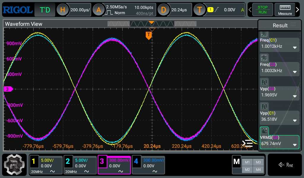
According to the simulation which I’d take with a bucket of Salt (I really don’t think the C3M model is good) Maximum output is about 18W RMS into 8Ohms at about 0.5% distortion (somewhat better into 4Ohms), closer to 0.1% distortion at 1W, 2nd harmonic dominant. Of course it also claims a bandwidth of 5Hz to >300+KHz, and I highly doubt the high end of that.

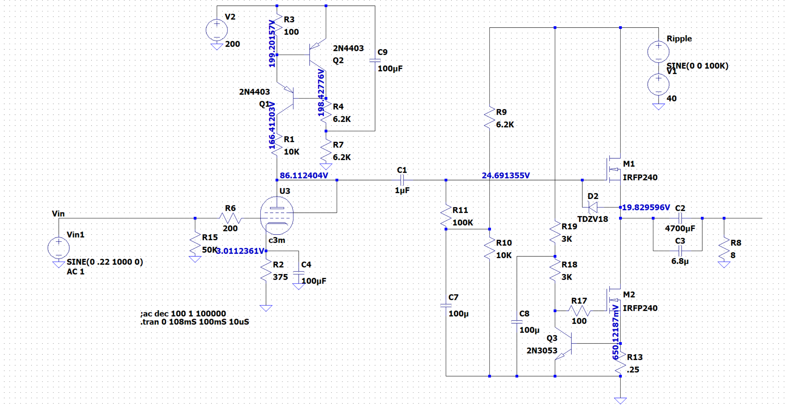
I’m Somewhat enamored with the linearity of the triode strapped C3G and the C3M is a similar tube without the Lampizator Tax because of it’s 20V heater.

Lots of things I am still mulling, I certainly don’t need a 200V supply on the C3M, but I want to build and test the voltage gain circuit, since I don’t trust the Spice model for the tube, and it gives me some headroom.

I considered adding feedback which could easily drop the THD by an order of magnitude, but I’d need to run the C3M as a pentode to get enough gain, might be an interesting experiment.
I could go to +20/-20V rails on the RHS and use a DC Servo to get rid of the Output Capacitor.

If I don’t care about driving speakers I can drop the 2.5A of current running through the output mosfet quite dramatically, which would save having to have enough heatsink to dump ~43W of heat across the 2 mosfets (wonders of class A).

11 Likes

This is the tube section on a bread board, the design has changed a bit.
Outside having to tweak the 100Ohm resistor to get the exact current I wanted, I dropped the primary voltage to 105, removed the 10K resistor, tweaked a few other values.

It does pretty much what I would expect, gain is about 18:1.
It’s ability to reject PS noise is impressive, at one point I checked the voltage rail and it had a 2V ripple on it (which is what the extra Caps on the breadboard are to resolve), which didn’t impact the output significantly.

It’s difficult to measure distortion (it’s at least -50dB probably significantly more) in the prototype for 2 reasons, the first is the little boost converter I’m using to generate the 105V has a bunch of high frequency switching noise in the audio band, the second is the massive amount of ground noise I seem to get off the USB audio device I’m using to generate the test Signal.

I was shocked at just how much noise there was, to the point I had to put the scope directly on it’s output to verify it wasn’t something in the circuit feeding back.

I have a couple more changes I want to make to the circuit, I’m going to use a different transistor in place of the 2N4403, because it’s close to it’s maximum 40V Vce with a 1V input signal, I’m going to push the anode voltage up closer to 100V, and run the primary voltage between 130 and 150V.
I’ll post an updated schematic when I’ve tested it with the new parts.

I’ll put together a workable HV power supply to get rid of the boost converter.
The way I intend to build this, the Tube section will be separate from the output section, and I have a few variations on that I want to try.

4 Likes

I’ve been trying to learn a little about design or at least able to semi-understand the language (but far from speaking it).

Conveniently enough this video dropped a few days ago. I see parallels from how she talks about appropriate part selection and tweaks for an established schematic and you figuring out how to get the job done on your build.

I always love the build threads, keep it coming.

4 Likes

This is the HV power supply, and one channel of the preamp on strip board. Once I have a final design I’ll probably have some circuit boards made up.
Tube carefully mounted to the right.

Output looks really good, distortion is below the noise floor of my scope (which isn’t saying a lot) even at the 36V Pk2Pk I intend to be the maximum output

The transformer is one of the ones I had left over from the 2A3 project, it’s higher voltage than is ideal, but the current draw is so low, the Mosfet in the capacitance multiplier doesn’t have an issue eating the 130V or so excess, even with the badly mounted heatsink.
It’s a different design than for the 2A3 amp, where I went CLC into the regulator, instead this is RCRCRC, with the last two inside a mosfet based capacitance multiplier and no regulation. Regulation isn’t necessary here (or really with the 2A3 amp), it’s class A, so current draw is constant, any excess voltage gets dropped across the CCS in the input section so any voltage from 130V to 160V is fine.

The output from the power supply is stunningly clean, I can’t really measure the ripple it’s in the noise floor of my scope.

Rather oddly there was as periodic noise spike when I tested the supply, but after some investigation, it’s still there with the supply turned off, so I have something pumping ground noise on the same circuit as the scope and the PSU, probably one of the wall warts plugged into the power strip the scope is plugged into.
It’s a big enough spike, I’m going to try and track it down tomorrow.

I’ll probably build one channel of the output stage, then go back and build the other channel. I’ll have to order parts for a dual rail power supply before I can get the power section working, I don’t have anything on hand that can deliver +/- 20V at the current I need.

6 Likes

And the class A MOSFET output section.
Works as designed.
I’m running this version at 20V, with about 1/4 of the current the design at the top is configured for. Still lots of power for headphones. Even with the greatly reduced output the aluminum plate is unpleasantly hot to touch, I’d guess around 60 or 70C. It’s dissipating about 13W into the aluminum, with no load attached, the speaker version as designed has to dissipate closer to 100W, I think I probably want to connect them to a real heatsink before testing that.

I’ll plug it all together tomorrow and verify everything works as intended, then build the other channel.

4 Likes

This is so fascinating to me, this little 3” cube of a few whatchamacallit pieces puts off that much heat :flushed:

Class A so so constant power draw.

The primary current for the amp runs through both mosfets and the big resistor on the board.
The big resistor always drops just 0.65V and its value dictates the current. It’s a 1 Ohm resistor currently, so 0.65V/1 = 0.65A flowing through the 2 Mosfets at 20V -0.65 that’s 19.35*0.65 ~13 Watts, nothing to dissipate that except the 2 Mosfets so they get hot.
That 13W results in ~4W of power at the output so a little worse than the optimal 50%, for a class A amp with a CCS. If I was actually drawing those 4W, then the Mosfets would only have to dissipate 9.

I did some more playing with it, and it takes a long time to get up to that temperature, I actually think the issue is just the sheet of Aluminum can’t dissipate the heat to the atmosphere, given all it can really do is radiate the heat up, so I expect a decent sized heatsink to perform a lot better. The Mosfets themselves are rated for 150C, but I’d like to keep them under 90C if possible.
The final build was supposed to put out about 18W into 8 ohms so you end up with 40V*2A and change >80W dissipated by the two Mosfets in each channel.

3 Likes

Testing both Channels of the Pre section

My new scope lets me easily capture the screen

About 700mV RMS input 1V Pk, which is close to it’s input sensitivity.
About 13V RMS out 18V Pk

Purple and Blue are in
Yellow and Cyan out

The disparity in the inputs is from the Pot.
The slightly large disparity in the outputs is a function of the tubes matching, they are actually pretty closely matched.

The bandwidth looks good, I didn’t check the actual -3dB point, but looking at it at 20KHz, it’s going to be up well past 30KHz, and well below 10Hz.
2nd Harmonic distortion creeps up to about -55dB ~0.2% at 18V out, and somewhere well below -60dB’s (I can’t easily measure it) for rational output levels.

It’s worth noting the noise on the input, most of that is from the USB power from my PC into the sound interface I’m using to generate the the signal, I have a battery powered signal generator that doesn’t do that, If I get time later I might post a comparison to demonstrate how bad connecting to the USB port on your PC is.

7 Likes

Excellent, super excited for you and i am so very curious to see the results of this comparison if you happen to post it. I knew i wasn’t “imagining” the difference when i got off my PC that a dedicated streamer made and even more so when i avoid USB on certain products :+1::+1:

It’s so awesome to follow along on these DIY builds, they get me excited to make time and get hands on again like i used to in my younger days :pinched_fingers:

2 Likes

Would that be considered pretty good for a pot?

1 Like

It’s negligible it’s an Alps RK27 100K in the “sweet part” of the travel probably typical, remember hearing is logarithmic, that’s probably a 1% linear difference.
It’s not the pot I intend to use in the final assembly, I have a stepped attenuator for that. It was just easier to mount on a board to connect to a source without a panel to mount it on.

For point of reference, the tubes are matched to better than 2% based on that output, 5% would be considered an extremely good match.

3 Likes

With a stepped unit how close do you expect matching there? I am guessing it is just at the mercy of the resistor’s tolerances and any matching?

1 Like

It wasn’t a very expensive unit, and I haven’t checked it yet, but I will at some point.

1 Like

Quickly checking it with a meter, it’s dramatically better than the pot, much better than 1% at every step, somewhere between about 0.1% and 0.5%.
For comparison the pot has a significant difference in overall resistance left to right and the to two channels can be as much as 5% disparate, Worst near the bottom end of the travel.

I guess that’s about what I should have guessed since the stepped unit is supposed to be using 1% resistors.

3 Likes

That is pretty good. I guess the worst thing is if a resistor on one channel has a step where a resistor reads low and the next step it reads high, but on the opposite channel that same step is a much closer increment.

But with such tight tolerances it will probably only offend machines and measuring tools.

And I finally listened to it today, Focusright PC interface as the source through HD6XX.

I’m using the two bench supplies for the Tube heaters and to power the output section. They are switching mode and dumping a ton of noise into the circuit (most of it high frequency and inaudible).
I should have all the parts for the low voltage PSU, so I’ll build that over the weekend.

Short version, I think it’s extremely promising. Surprisingly full bodied in sound, but still presenting with a lot of clarity. I ended up listening to it for a good 40 minutes which I wouldn’t have if I wasn’t somewhat enamored by its sound.

A slight hum/crackle through the right channel, could be almost anything, it’s not worth trying to track down when it’s put together like this.
I also need an additional ground point on the output boards, and that could be contributing.

I need to hear it with better headphones, which won’t be until after I convince myself it won’t destroy them.

Aluminum plate now hits about 170F it’s dumping a good 25W into it, which is still inside my comfort zone and I have a pair of larger heatsinks for the final assembly.

11 Likes

:rofl: :joy: :rofl: I’m genuinely laughing and crying so hard, spoken like a true engineer good buddy! :nerd_face:

My ex-wife was a EE and i remember a few of her MIT classmates and her working on a big project decades ago and i swear your statement and nonchalant attitude took me back an easy 25yrs standing around watching them work on a project i was privy to.

Congratulations on your success, almost there :pinched_fingers:

2 Likes

Well I’m in my 2nd attempt at a low voltage PSU, But with just the input board connected to the output board (no gain) it’s completely silent, and sounds good.

First power supply was a failure because of all things I had a bad strip board, one of the tracks was so badly manufactured, that it failed in multiple places as soon as any current was passed through it. It took a long time to diagnose that issue.

The second one, I’ve modified the design, I’m now using a Mosfet in the Capacitance multiplier, instead of a Darlington transistor, which is an unusual approach.
There are downsides to this, but none of them (except the additional heat) really apply to an unregulated PSU feeding a constant load. And Mosfets have in effect infinite current gain at low frequencies.

I measure somewhere under 1mV of ripple under load (it’s low enough it’s hard to know how much of the noise is the supply and how much of it is just the measurement setup).

Tomorrows project is changing the resistors over on my breakout board, so I can get the tube heaters back in spec, and giving it another listen end to end.

7 Likes

Finally working end to end.

I had a bit of a scare, when I first assembled it, it had a nasty buzz and crackle through both channels, but was oddly completely silent with the input at 0 Volume, that had me flummoxed for a while, the amp is amplifying the same at 0 volume as it is at 100%, any hum should be present regardless of the input volume. My initial guess was some weird interaction between the two supplies.

It took me a good hour to track that down. When I decided to build the amp on various strip boards it was to facilitate experimenting with different configurations. Making it easy to swap out a pre board or a power board etc.
So I used the little terminal blocks to wire everything together. Nothing of course is labelled and for some reason I thought both the terminals on the back right of the pre board were additional grounds. However it turns out that I had wired one to the input signal so I could easily test it, so when I reconnected everything the ground into the power section was actually the input signal

When I finally assembled it properly, it pretty much just worked. There was a slight hum at some positions in the middle of the volume knob, dead silence at <10% or >50% volume, but that one I’ve heard before, the Pot acts as an antenna and picks up mains hum, solution provide an AC ground path.

After that fix is was dead silent.
I spent the last couple of hours listening to it through the Raal CA-1A’s, and its a very compelling listen. the C3M pre section opens up the sound but you don’t lose the grip and control it has.

I’m still running it off 1/2 the intended power supply, 20V instead of 40V, it’s limited to about 7V RMS and 4W in this configuration, which will deafen you with the Raal’s (which are even less efficient than the Susvara) and provide way more current than required. I’ll build the other half, and I want to experiment with +/-20 vs +40 power options, though my best guess is the +40 version is where I’ll end up.

I have some bits and pieces for a case turning up next week, and I might start moving it into a case, but I’m tempted to have some circuit boards made up for it first. I guess I should be able to move it into a case, then incrementally replace the strip board pieces if I can get them to fit.

7 Likes

I am happy to see the progress from prototype, to a solid build, to final iteration. As well as the little oopsies or coming to realization moments.

I get the feeling all these are fun projects to play with and experience different concepts. Will you ever do an all-out-balls-to-the-wall build?