Build Log: Whammy Take Two

Over the last four to five years I have very much enjoyed the Whammy HPA I built back in 2021. I did also have the occasional issue with it. The lack of front panel power switch led to me getting a custom FP so I could fit one, as well as adding a power indicator light.

More deep seated items for me have been that having the power supply on the same board and so close to the audio path means it is very easy to have audible interference turn up in the background. Shielded power cables help with this but still, not ideal.

More of an issue has been that there is very little clearance around the opamp which limits you pretty much to standard format DIP-8 chips. Anything else needs a riser which is far from ideal.

Lastly the default specifications have quite a lot of gain meaning that any headphones with a low impedance or IEMS have almost no volume pot room at all.

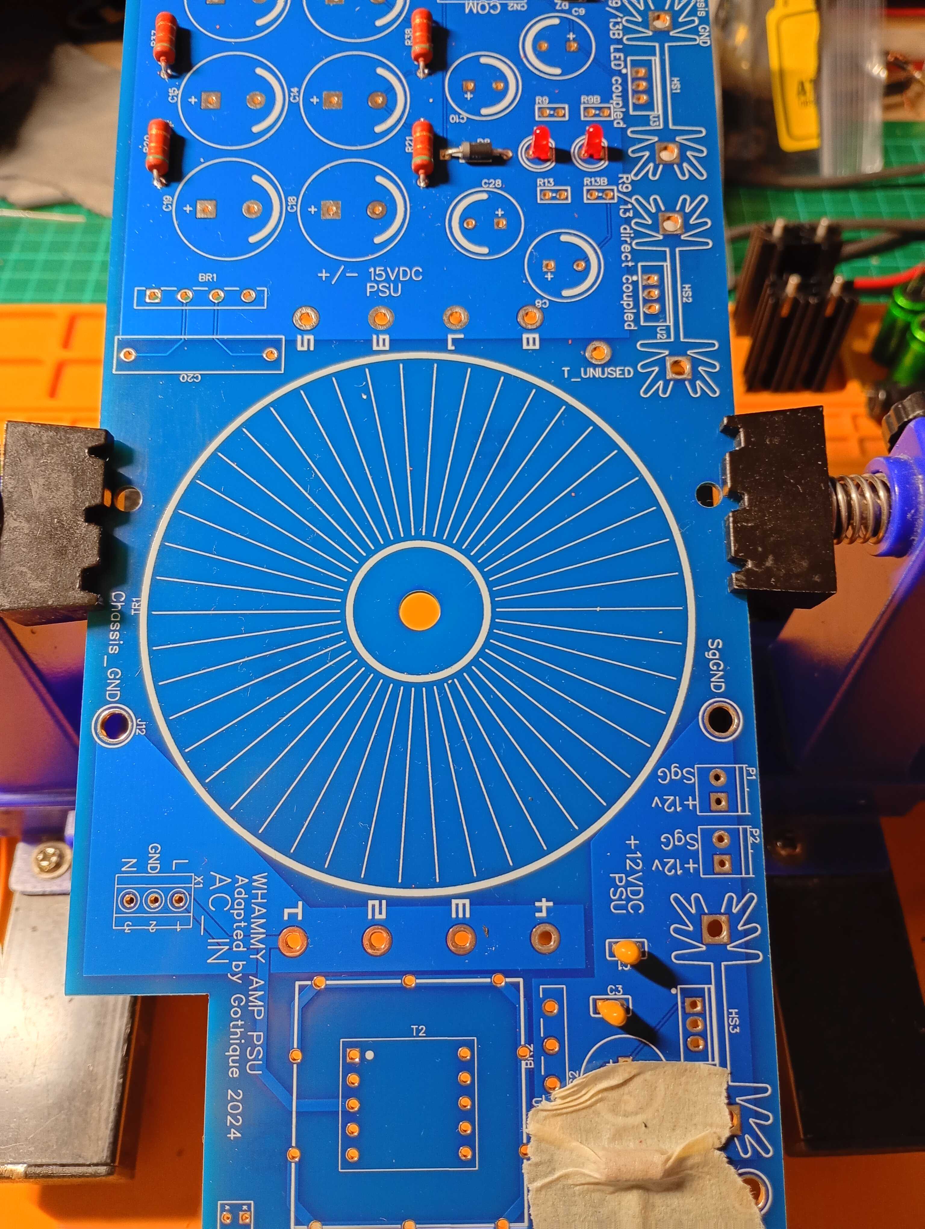
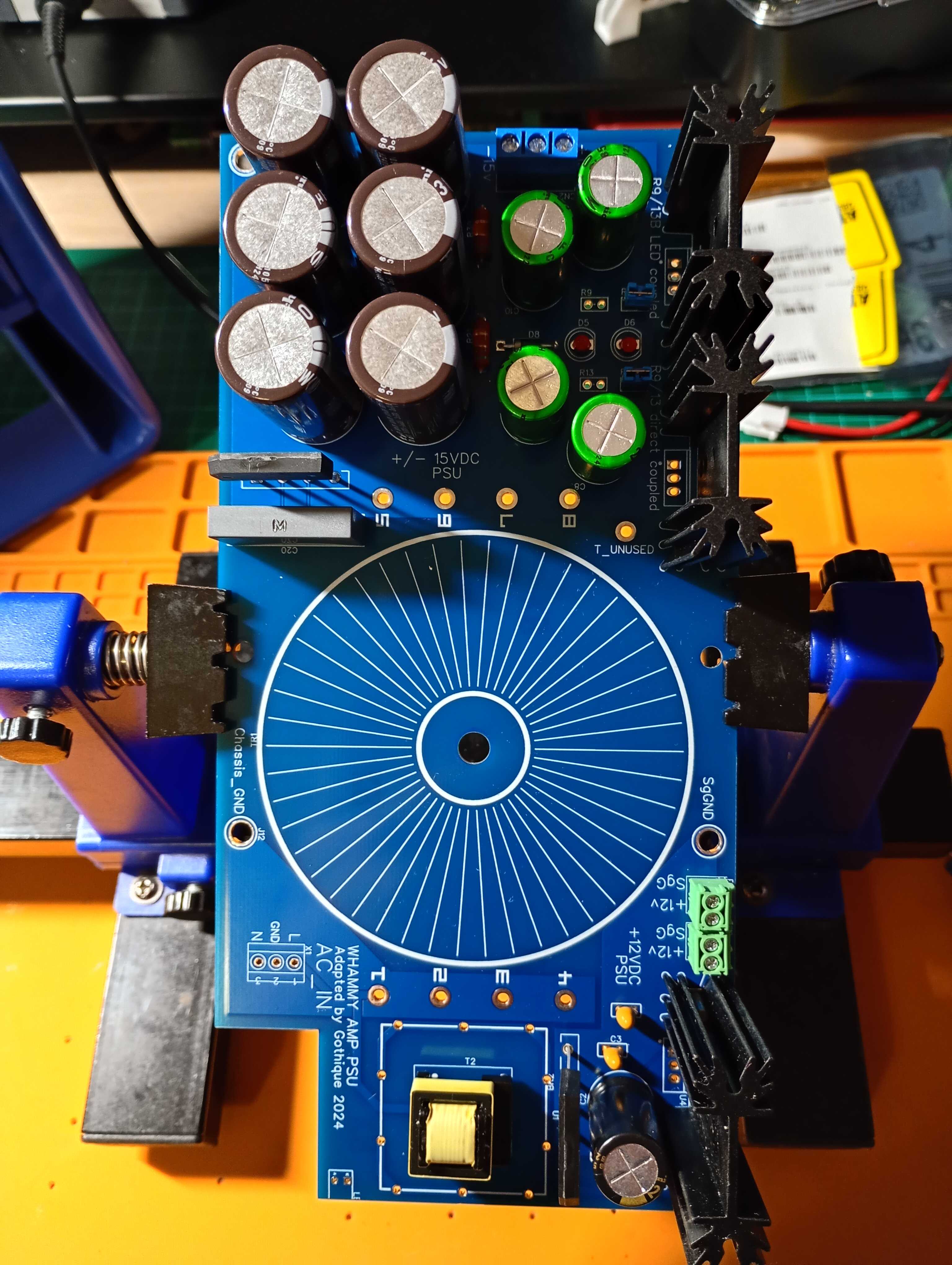
So I decided to make my own version. I wanted to split the power section off, allow for switchable gain settings and try and make a shorter audio path with more space for larger boutique opamps. I spent about two years copying and redesigning the schematic, testing my pcbs, redoing them. I designed a small 12v supply for the front panel and relay switches. Added in balanced inputs with a transformer step down as an alternate input and dropped the rca output entirely.

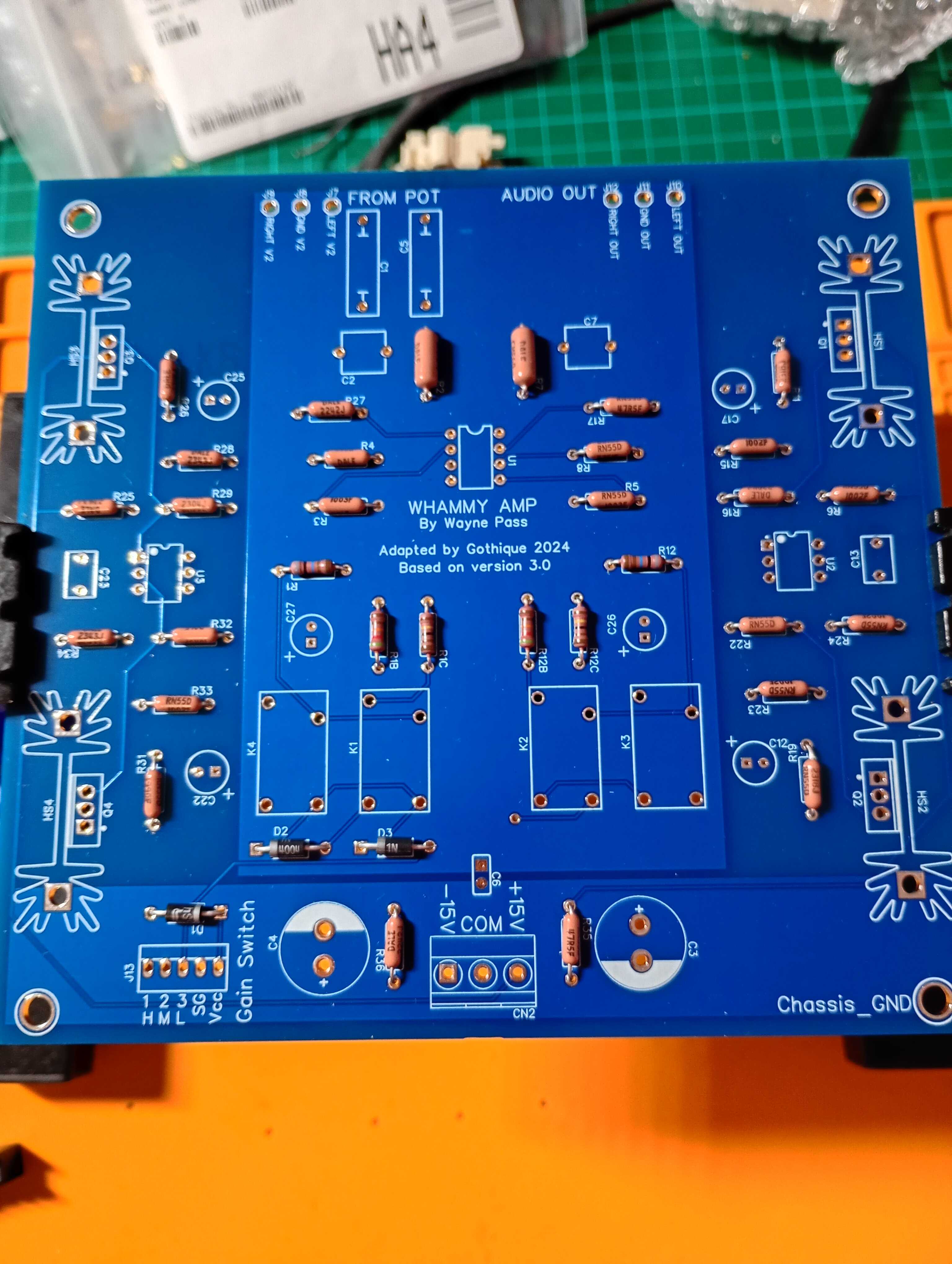
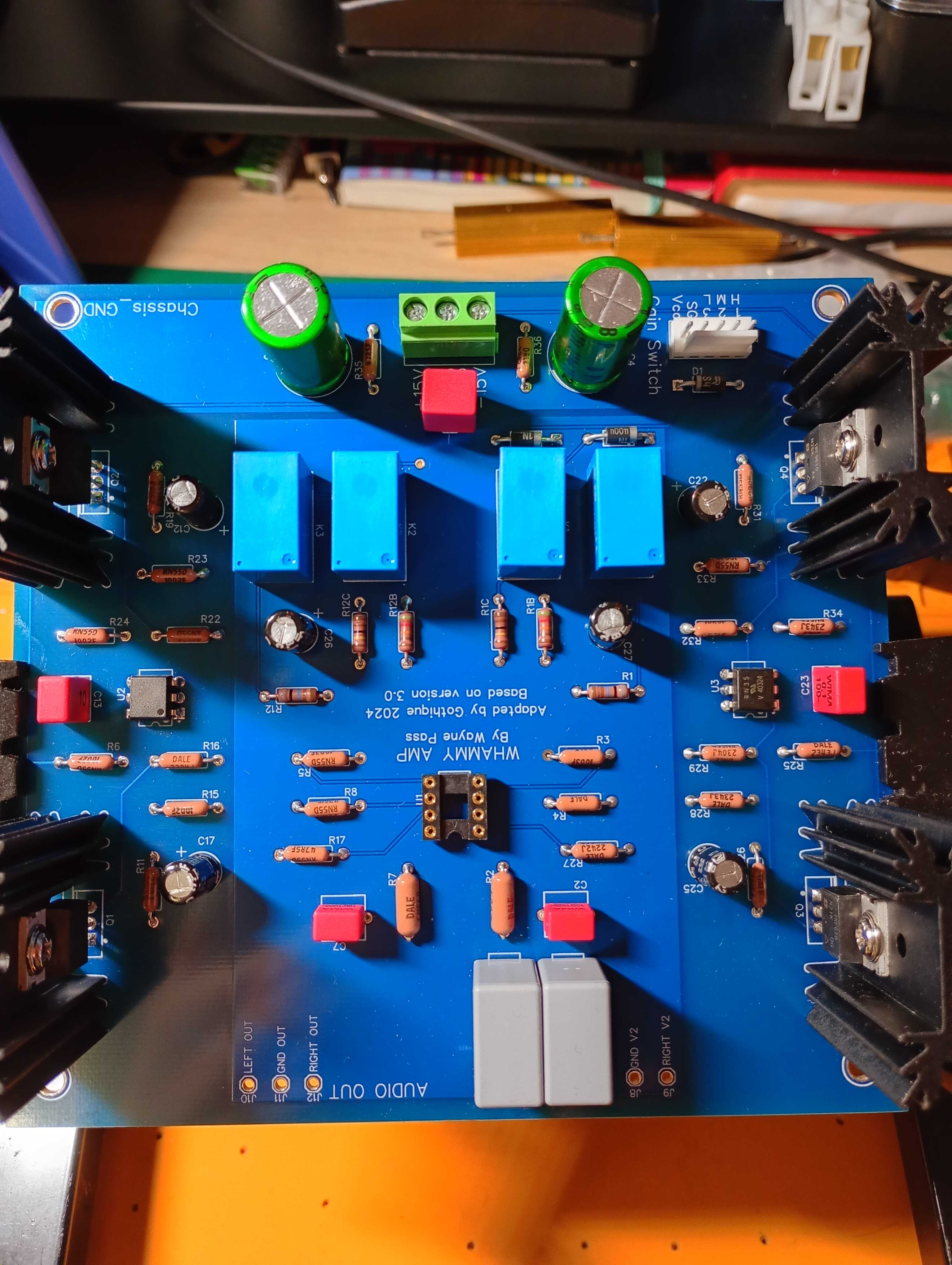
Then I started sourcing all my parts so I can build my personal, definitive Whammy. It took a while as I decided to get the best components I could afford - I don’t plan to build this again so it might as well be as good as I can make it! On the whole the parts in the original BOM are of excellent quality so it was mostly just a tweak here or there. Middle of last month I finally had everything ready and now I can start building.

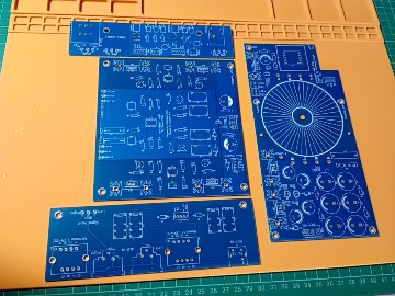
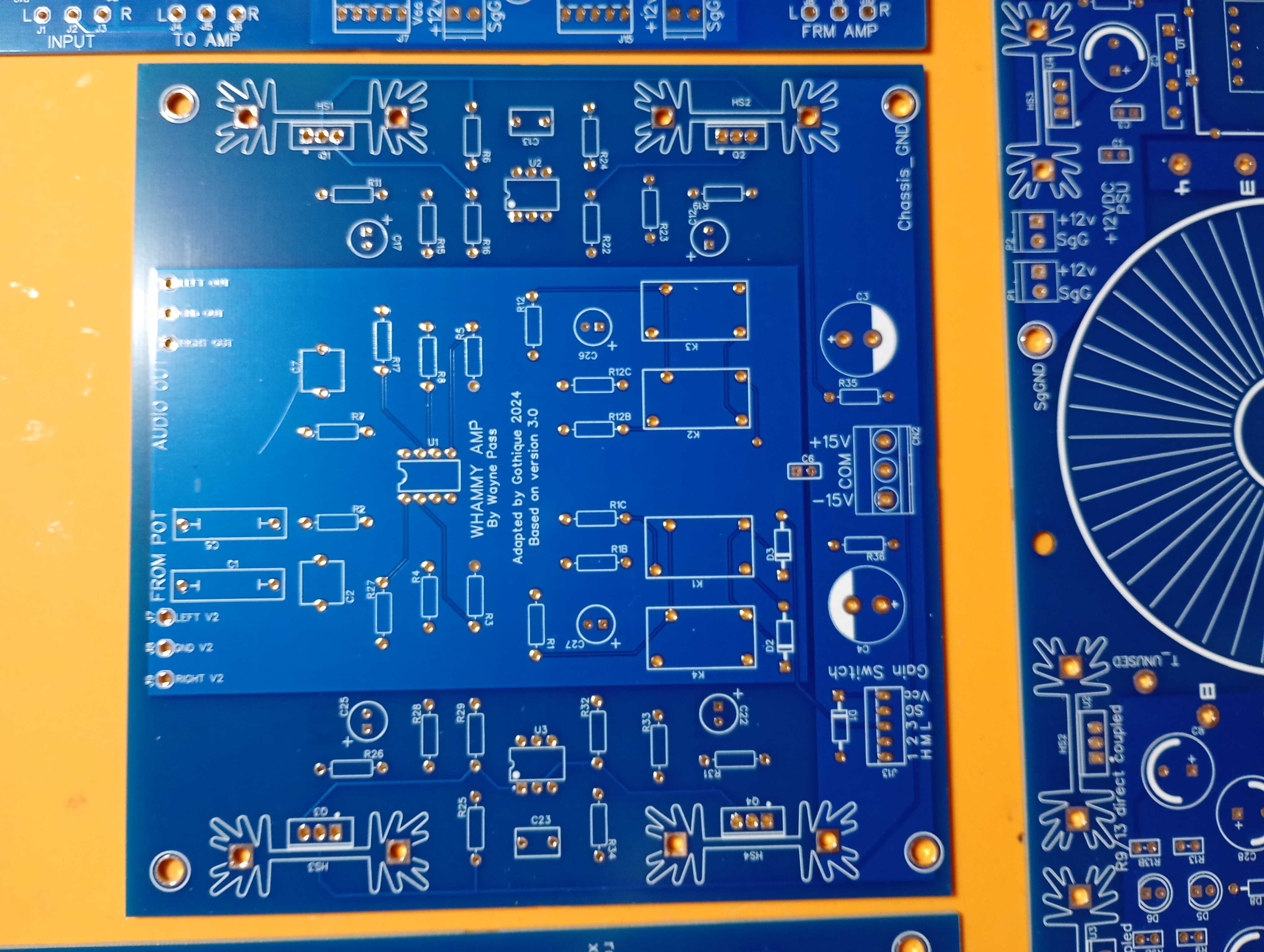
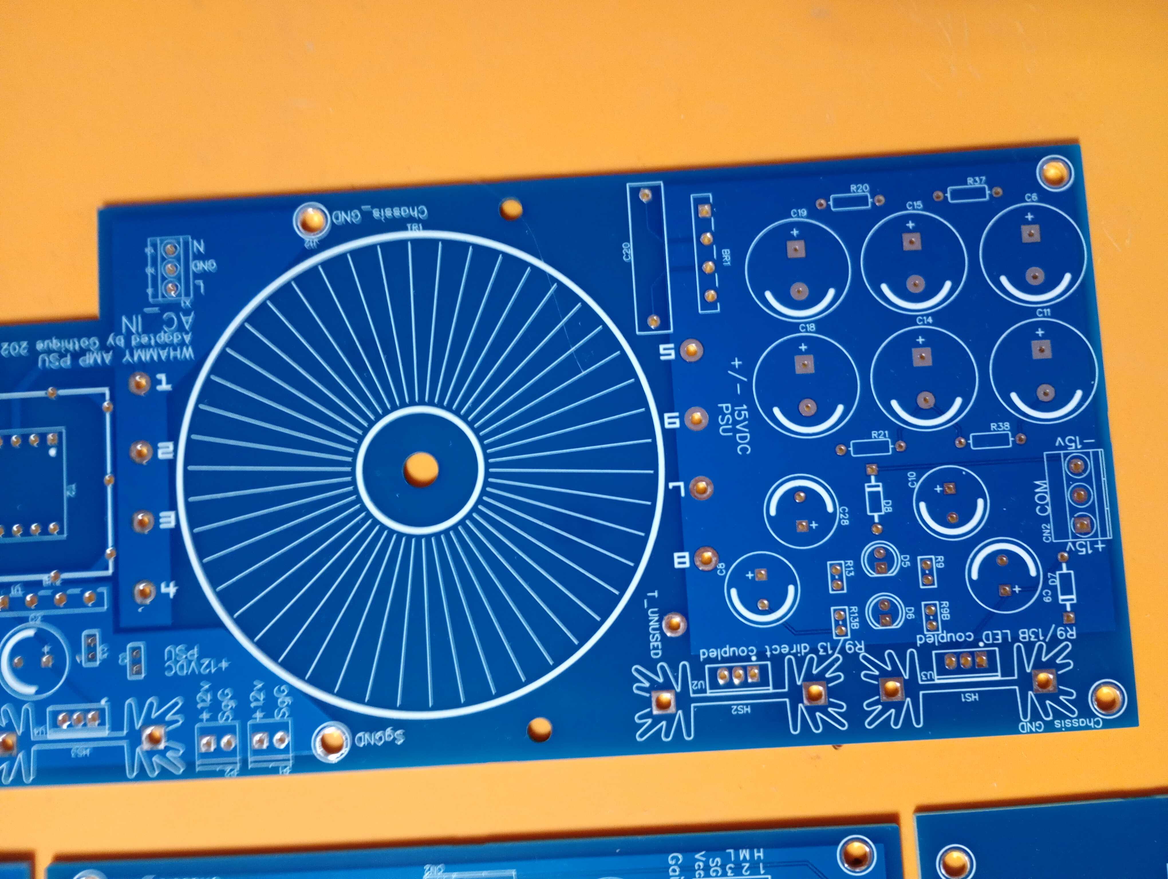
From top: front panel board, amplifier board, inputs board and to the right, power supply. The inputs are relay switched as are the gain settings. There are three, low, medium and high ranging from gain of roughly 1.8, 4 and 7 (the last is the default specification). The gain is determined by resistors that are not in the direct audio path. This makes it possible to avoid having a complete switching break in the circuit that could lead to pops and other headphone unfriendly artifacts by making use of parallel resistors for mid or high gain.

So there we have it. In theory it should just be a case of assembling it all now, but as I have not yet been able to test all the elements together, you never know! My plan is to build the amp, the psu and then front and back panels. Testing as much as I am able as I go. Once all are built I can get them mounted on something for a proper final test before hopefully being able to move on to housing the amplifier.

14 Likes

Following, but bigger pics please! lol

3 Likes

Yes not too sure why that one is that size. Same on my phone too. Odd! The ones I took immediately after are fine:

9 Likes

Amazing the technology available to us now that you can design and order your own PBC designs like this!

4 Likes

It really is amazing and crazy!

I can find the design on an internet forum, given out to teach for free. Design and test a schematic on a computer, all of the software is open source. I can then order pcbs in batches of five from China and they come to me at home, the parts from Mouser and Digikey arrive from the US. The world has become so small and much of the internet is still a wonderful community of people sharing knowledge :smiling_face_with_three_hearts:

5 Likes

Following as well, looks very interesting and am very curious to see what comes out!

3 Likes

As a weird asside when I order from PCBWay and Mouser at the same time, often the PCB’s will show up before the parts, and I live in the US.

I am always stunned how painless it is to order PCB’s, and how cheap (assuming your making more than 1). Having said that I always seem to make the same 2 errors when I order PCB’s and I seem incapable of seeing them until I have the first batch of PCB’s in hand.
Either I get the legs of the transistor in the wrong order (use the wrong PCB symbol) or i get the big Mosfet or Regulator oriented wrong so my cunning plan to mount them to the case as a heatsink becomes unnecessarilly painful.

6 Likes

I love this. Looking forward to seeing this progress :heart_hands:

2 Likes

First up, amp pcb. So the first photo is from mounting resistors and is perhaps a good point to talk a little about some of the smaller changes I made to the original Whammy design.

You can see the opamp section has been given a ground plane, rather than just ground traces. It should help in picking up any stray interference. There is also a ground plane for the power section with a small capacitor connecting the two to soak up any parasitic interference before it reaches the amp section. I also designed it to be symmetrical in layout. This really would have minimal effect. Arguably it is good practice to have the signal path be of equal length for both channels but mostly I did it because I think it looks better. In the middle you can see the opamp is now much less tightly packed so that larger opamp assemblies can be mounted.

Here you can see the rest of the components mounted. Most notable change is the four relay switches. The path to ground from the opamp is where gain is best controlled in this amplifier so these sit on that. There are now three paths to ground with one always active and two switched, we’ll call them a, b and c. With both switches off only a is open and gain is low. Switch on the b and two are open in parallel that give mid, a+b. Second switch on and it activates c to give a+c and high gain. Control comes in from the front panel via the white header you can see top right.

So there we have the amp board. I was able to confirm it works in a basic way by powering it using a noisy adjustable dual rail psu I have and sending a signal through each channel to be read at output. Both channels pass the signal and the wave form looks correct (if very much affected by the psu noise) but I won’t know if they do so cleanly until I can put everything together.

14 Likes

…and you say you bought five PCB kits. hmmm :smirking_face:

3 Likes

I see an error on your PCB…..

Waynes last name is Colburn, not Pass, he just works for Pass.
I suspect you’ll be able to work around that error though….

Looks really good so far.
Most of the noise it’s likely to pick up will be from the AC side, probably the transformer, though it’s low enough voltage/current, I doubt it will be an issue, physical layout in thebox will likely have more effect that the PCB layout.

Grounds are the only other thing you need to be careful with the bigger the PCB the worse that problem, but if you are careful if/where you couple signal ground to power ground it shouldn’t be an issue.

5 Likes

Dammit of all the things to get wrong! Hah! You know I spent about six months on this pcb? This was the third printing of it and at no point did I question the quickly typed label I put on it way back at the beginning. :rofl:

Thanks, appreciate the feedback too. The noise was very definitely from my diy dual rail test psu. It uses two buck power converters with little in the way of filtering. I couldn’t afford a proper dual rail bench power unit, one so I work with this one for now.

My previous test version of the layout seemed to be ok with (approximately) the same signal/power ground connection location so I am reasonably hopefully that will work out.

Wait until we find out if it works first lol

Parts cost has been around 600 euros plus chassis. So total cost including pcbs is in the region of 600 Euros.

8 Likes

You can use two single rail bench power supplies (which is often cheaper), you just need to ensure they don’t do something stupid like ground the black terminal, basically you wire red to black, ground that black and let the other one float.

That works with the cheap bench supplies I have, but the cheap bench supplies are not exactly noise free either.

5 Likes

That’s an idea. I should look into it.

2 Likes

I am so impressed, that’s quite an accomplishment and far beyond my abilities. I look forward to seeing how the rest goes, and the finished product.

I was about to ask who Wayne Pass is, I’d never heard of him! :wink: :rofl:

2 Likes

You could get a pair of Peaktech 6227’s and daisy chain them.
Or in a single unit: GWInstek GPE-2323A

3 Likes

Next up, power supply. This is two supplies. Everything from the toroid up is the amp dual rail supply. That on the part below is the positive 12v rail for relay switches and led indicators. Beside the LEDs you can see mounting points for two pairs of jumpers. These relate to choices that can be made on the original board for how to complete the power supply. I chose to retain them here. Only one is needed at a time. I chose the variation with LEDs and so chose the matching jumper.

A couple of decisions. Instead of four separate diodes I chose bridge rectifiers to save space. The 12v supply has an additional grounded shield to help prevent electrical interference inside the chassis.

And the final board. I choose a medical grade toroid transformer from Hammond. It has the added advantage of being relatively compact and low profile. I like to always use plastic fixing nuts for these as then there is absolutely no way to form an accidental additional winding through contact with the chassis. You can also see the cute little EMI shield on the baby 12 volt transformer to the right.

The transformer is not yet connected so I could run tests. Both rails work and provide around +/-14v which is within tolerance for this design.

Next up will be the front and rear panel boards.

11 Likes

The plastic standoff of the transformer is a good idea! Not for shipping but sonically it’s the cheapest way to get a non ferrous bolt I guess.

3 Likes

I guess it would be more accurate to say nylon than plastic? They close extremely tightly, I’d be impressed if they came loose by themselves.

4 Likes

LOL I was going to say polymer and changed my mind. An example of you think long you think wrong.

1 Like