Always exciting when the M10-Bolt-Winding welds the chassis to the PSU-board ![]()
2 Likes
Luckily thermal stickers exist ![]()
No other update just yet. A slightly busier week for me at the moment. Hopefully I will get to my workbench later in the week.
13 Likes
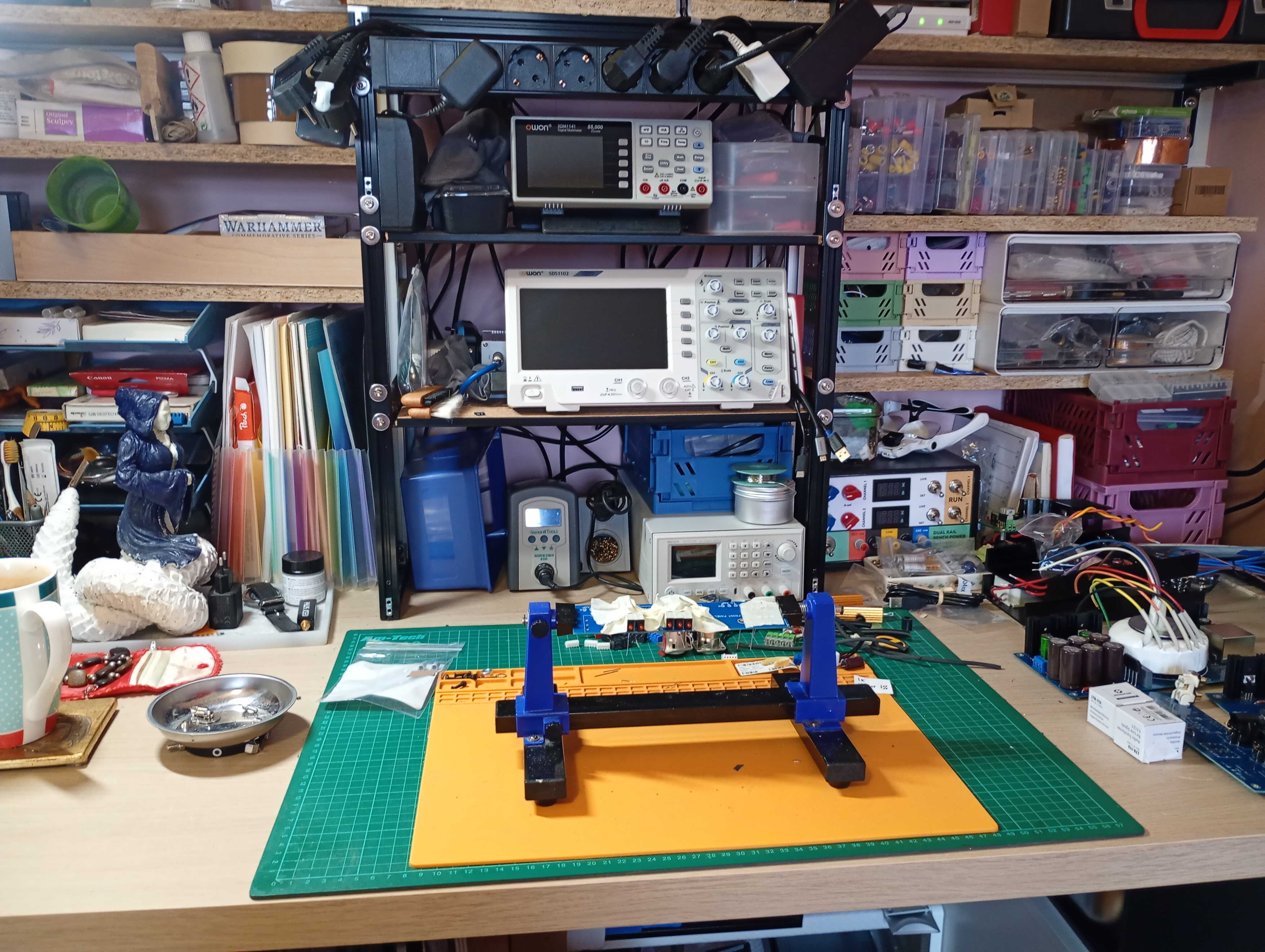
Still catching up! We had a minor leak I had to sort out yesterday so I didn’t get around to everything. Workbench needed a good tidy as well as a new power strip mounting on the frame so I got that done. I find that ordering my workspace is always the first step I need to take to get to work on something. Without that my own thoughts and plans also lack structure. I built it from 2020 aluminium profile and an Ikea desk… board? Sheet? I’ve forgotten the English word ![]() Buroblad! Anyway. I made one last year and that has made my projects so much easier to do… buuuut also led to more ambitious projects and more in parallel.
Buroblad! Anyway. I made one last year and that has made my projects so much easier to do… buuuut also led to more ambitious projects and more in parallel.
Nearly at the end of side quests now so updates will resume…
12 Likes
every time someone posts a pic like this, my voyeuristic tendencies kick in and I start looking through their shelves, or closets. no judging, just nosy. lol
Your workspace is so much clearer than mine…..
I mean, I assumed everyone does this? I know I do. I also secretly judge but will never own up to it ![]()
It is now lol
4 Likes
Despite another couple of distractions (I wanted to finish a couple of 3U desktop cabinets and my PC decided to spend yesterday failing in a really obscure and hard to track down way) I did manage to get the next board done. The front panel pcb.
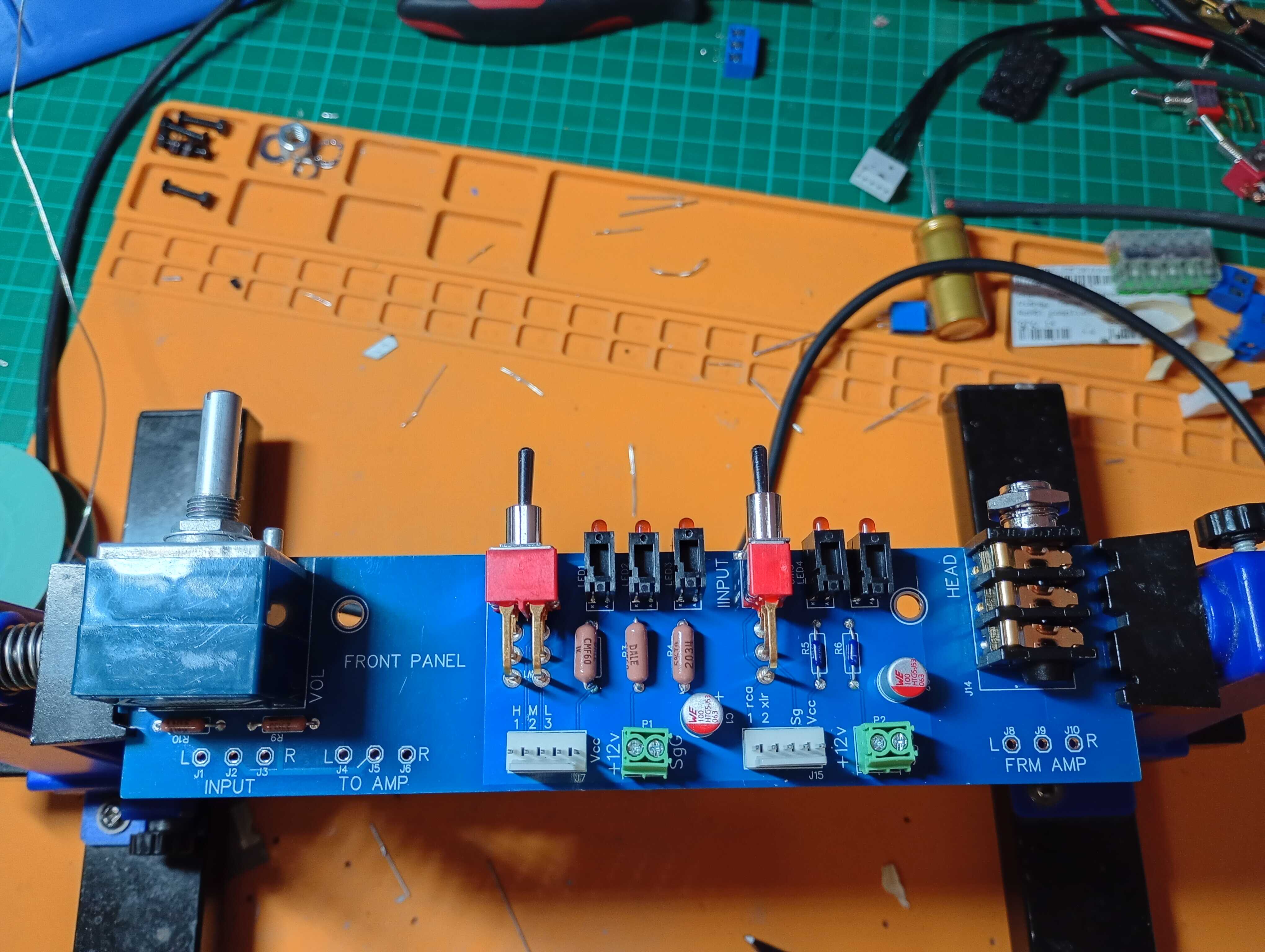
You can see here left to right the audio input and volume pot, a 10k RK27; the gain selector and indicator lights plus header; the input selector, indicator lights and header and finally the audio output from the amp to the headphone jack. There is no return as I opted to not include any audio out from the amplifier as a whole. I love the Whammy as a headphone amp but in my setup I find it tends to make my speakers sound not quite neutral when used as a preamp.
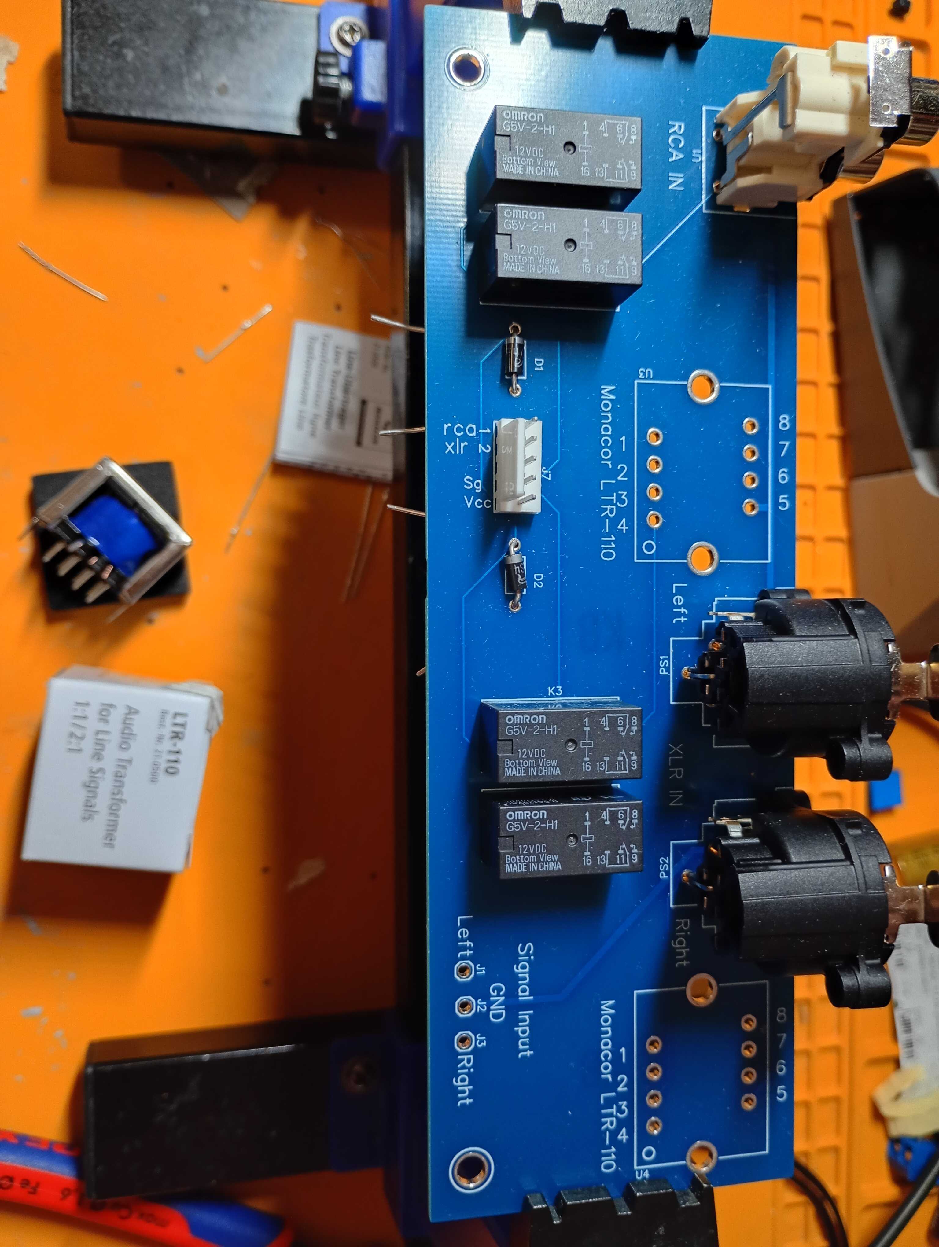
Next up will be the rear panel board, seen below as I prep it. For the step down transformers from balanced XLR inputs to RCA line level I am using a pair of Monocor LTR-110 transformers. These are good for both step down and pass through audio transformers for balanced inputs. Thomann stocks them and they are really good value for the build quality.
11 Likes
And the back panel pcb finished:
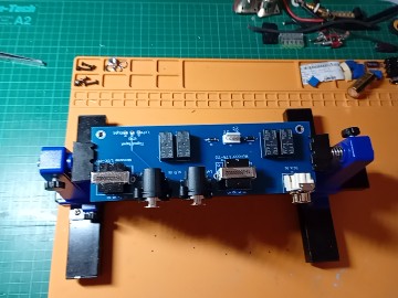
(another photo that decided for some reason to be smaller. Not sure why. Phone is trying to be clever I think)
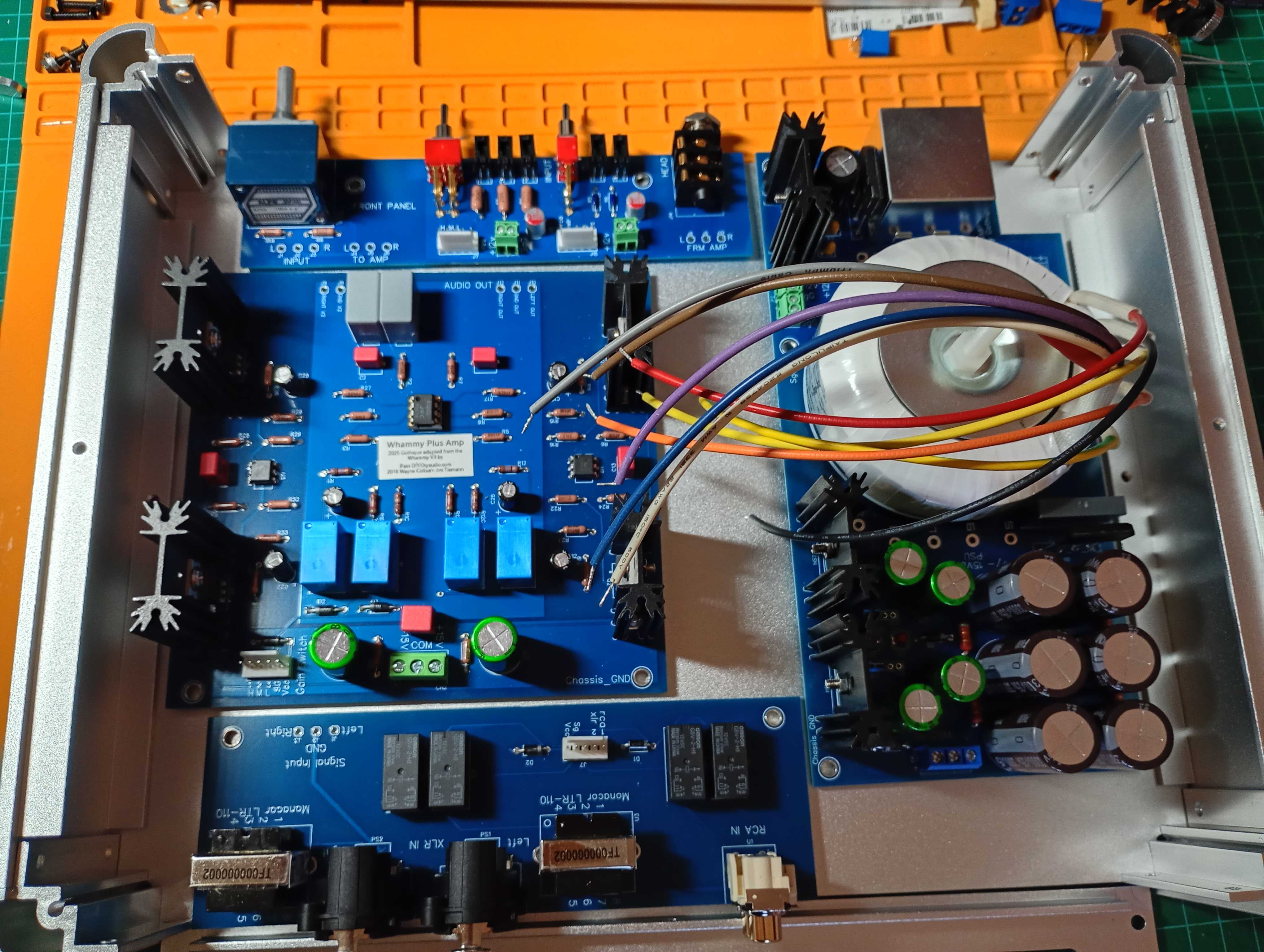
Next up is working out the arrangement in the chassis. Once I am sure and once the weather warms up a bit next week I’ll get into the garage and get the pcbs mounted to the base panel. That done I can safely connect and test the whole setup instead of as discrete parts. I also plan to cut and install an aluminium divider to fit between the power section and the amplifier.
11 Likes
I’d verify you can here a difference when you add it before messing too much with it.
From my tests it takes significant wall thinkness to really provide isolation (3-6mm), now my PSU was putting out more voltage and current, and I’m sure that is a factor, but I could for example hear no difference in noise floor with copper foil around the transformers as a shield.
5 Likes
Also copper is way mo’better at shielding than aluminum and you can probably get away with 2mm.
1 Like
I will take that advice, thanks. The piece I have is 3mm thick.
Indeed but also much more expensive and harder to find for me!
2 Likes
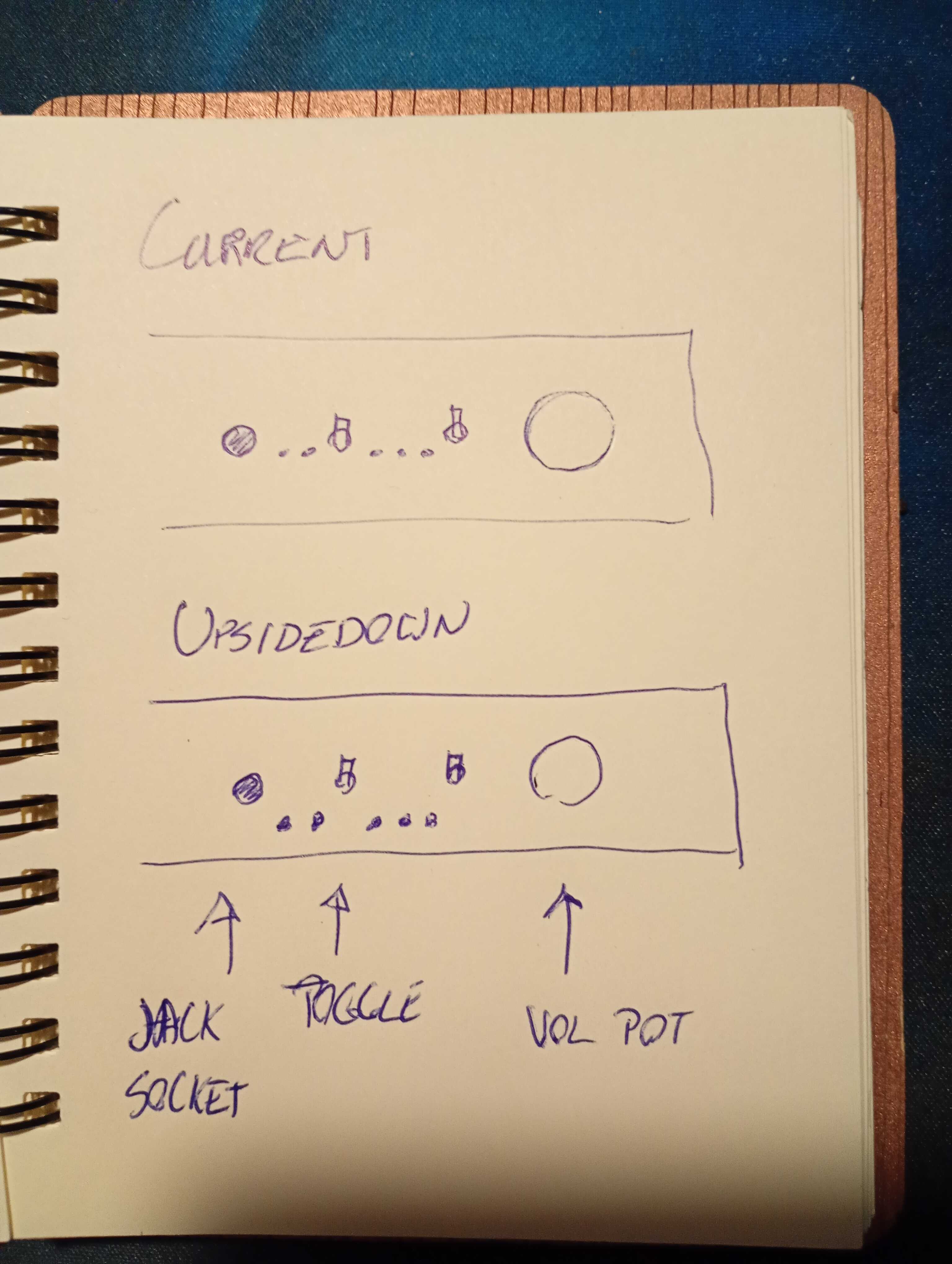
Due to changing circumstances my workspace is somewhat upside down at present. We’re moving furniture around so my desk is somewhat of a storage space for a few more days. However, I did manage to find space and time to start testing.
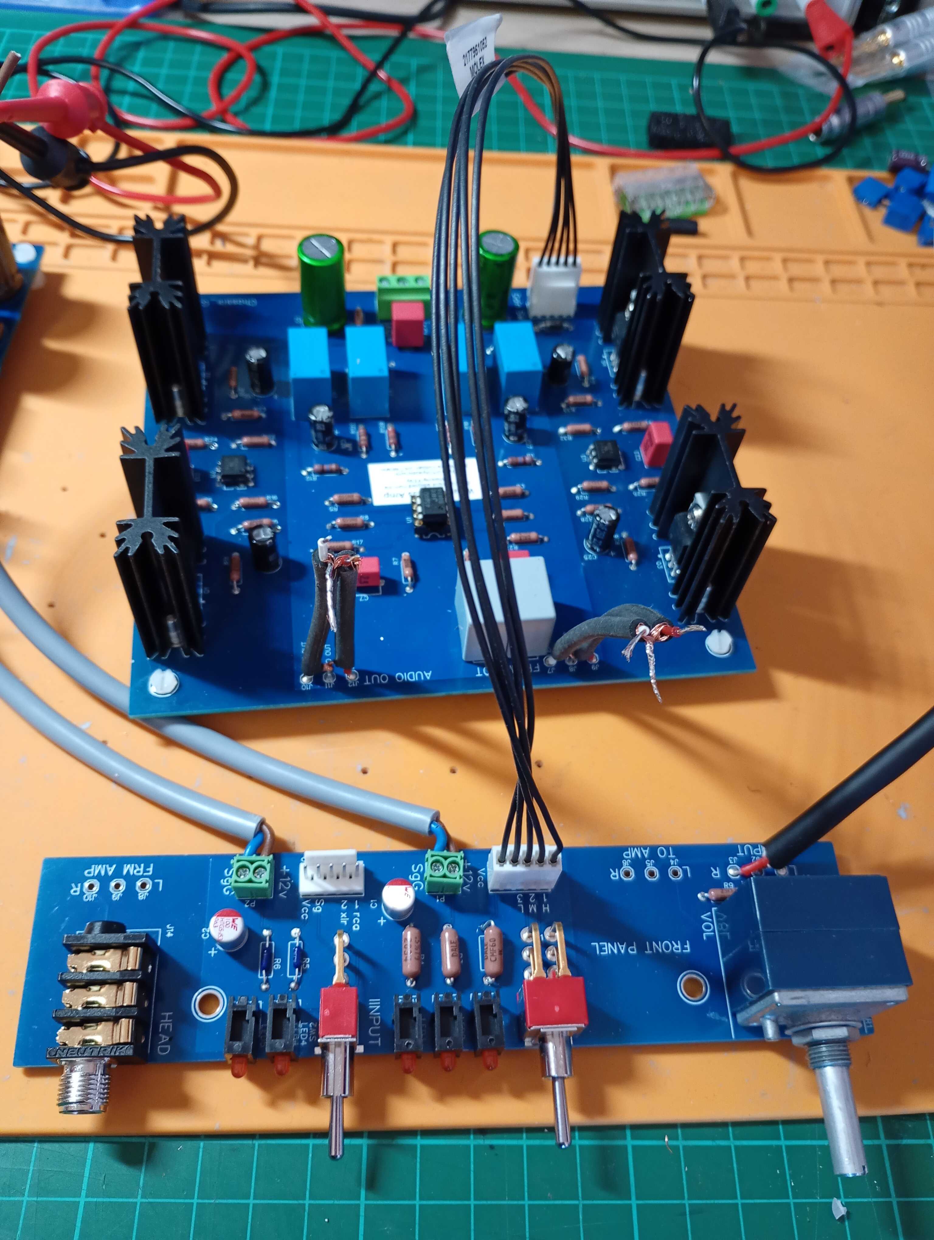
I initially cut and installed some of the cables that will run between boards. At first these are only soldered at one end to facilitate tests. You can see here I am testing the front panel and main board. Test one, make sure the switches and toggles work as expected.
And so I immediately find a very silly fault. These fancy leds are wired in reverse of my expectations so while I have confirmed they work… they don’t work on this circuit. So back to the drawing board, pcb adjusted, gerber uploaded and an order put in so I can replace this one and I have some lovely desoldering to do. Fortunately I do have spares of the smaller, more sensitive parts so it is only the easier, larger components I need to reuse. I thought it was all going too smoothly so far!
Oh, the switches do seem to work though.
10 Likes
Check they don’t come in two variations, I always have issues in KiKad because transistor legs are never consistent and the place that’s actually set is on the schematic, not in the footprint as you might expect.
And even after I know that I still mess it up because I can never remember if the datasheet is depicting them from the top or bottom.
2 Likes
Yes! It was exactly that issue that got me, it was an incorrect footprint. Had to manually swap it over. First time I ran up against this so now I know for the future.
2 Likes
couldn’t you then install them from the bottom up and not have to redo the pcb?
1 Like