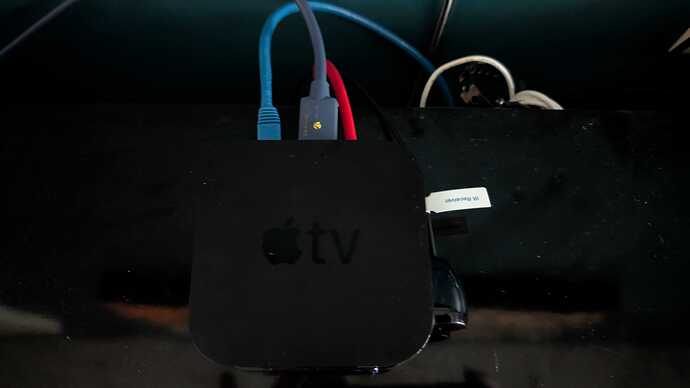
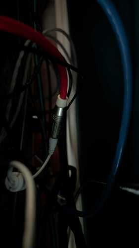
Well, I said I’d document it, so here it is.
Apple TV 4K 2nd Gen. (A2169 64GB) A number of posts and clips on YouTube on disassembly and why it’s a superior build to the new Gen 3.
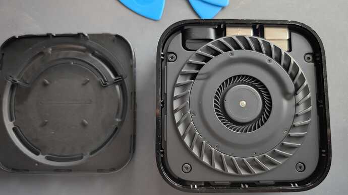
Bottom removed and the first thing you see is the fan assembly. Yes this version has a fan because it’s got a lot of HW that is completely sealed in an aluminum clam shell assembly.
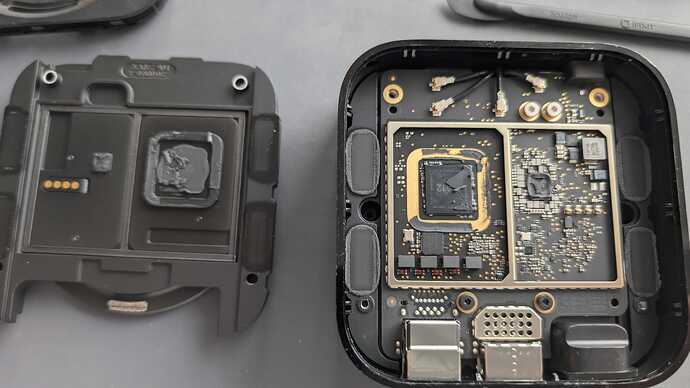
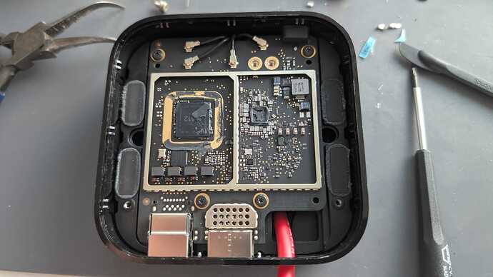
Fan assembly removed and that’s the logic section with the A12 processor on the left, note the hefty clock on the bottom left near it and all of the seals with heatsink paste for the processor and the aluminum shells as well. Everything is isolated and very well sealed. Also note that the noisy antenna connectors are outside the sealed areas. As Tuco Salamanca would say, tight tight tight design.
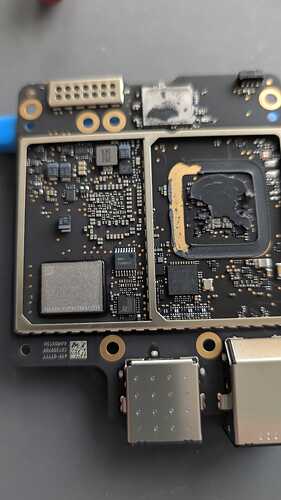
The bottom side of the same board, a log of stuff there, the HDMI connector and Ethernet jack. Not the RFI coating applied to the processor on the left side and again, everything isolated an sealed tight. All the screws had blue Locktite applied.
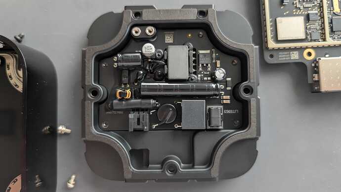
And underneath that board is the other half of the machined aluminum clam shell, five bolts again all with blue locktite. And then the bottom, which is actually the top when built, is the switched power supply.
Interesting design choice to keep the noisy board completely isolated from the rest of the system. The only connection is the two silver threaded tubes that “pass through” to the other board, so again very tidy design.
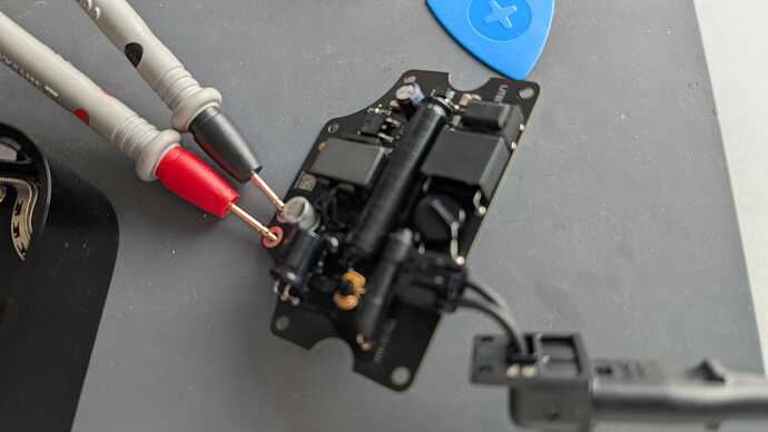
Here I’m just making a note of the + and - sides of the power feed through as nothing is labeled.
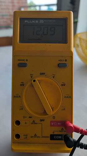
Confirmed voltage and polarity. It’s actually a LiteOn switched power supply.
BTW, fun fact. I’ve had this Fluke multi meter since 1990 and it’s still kicking!
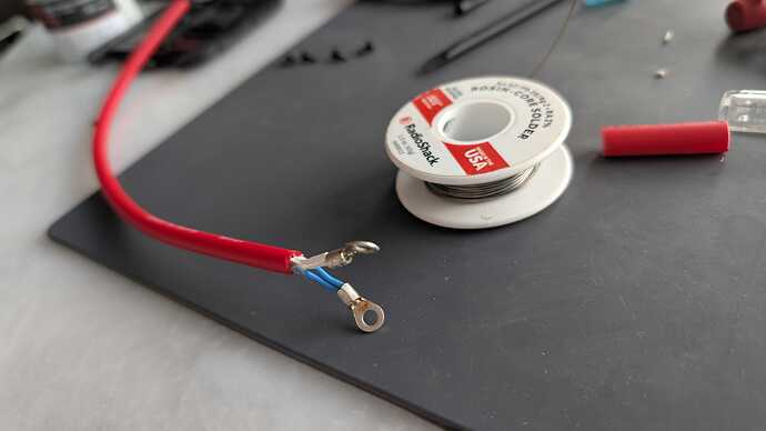
I built myself a cable with some Canare quad star cable I had and soldered ring terminals on it and used the screws to bolt them down in place of the power supply. The whole point of the project was to remove the power supply so I could use a quality external PS.
I was freaking out at this point since when I went to put it together the ring terminals were a fraction of a millimeter from the casing and I was so afraid of shorting things, spent about an hour thinking of how I would connect the cable until I realized that the metal half of this clam shell had pressed in plastic shell, maybe ABS or some other type of polymer. Anyway, once I realized that it was lined with plastic and I wouldn’t short it accidentally, it was a big sigh of relief. I was scared that any expansion with heat could short it but freakout averted. ![]()
…anyway, at this point it was getting late and I needed to pick up the wife, so I rushed the assembly and forgot to take pics of the reassembly process. A lot of screws with only the five bolts for the power board left over.
Here it is all back together.
Last pic, never miss an opportunity to score on style points. The power cable I terminated externally with a 2.1 DC connector which by a stroke of luck happened to have the same thread size as an Amphenol RCA connector barrel. So I used it as a means to make it all nice and neat and again, help with noise right? not the greatest pic here but it illustrates the point.
