I don’t think the “I am not sure either, but I am trying”-preamble is needed here.
Building a Measurement Adapter
Startpoint
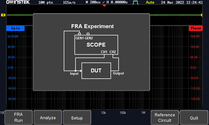
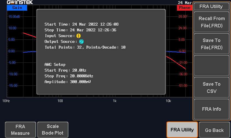
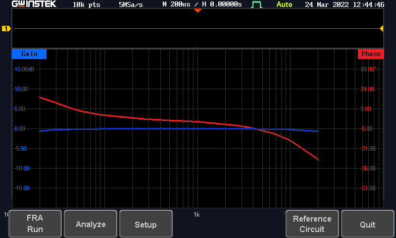
Since recently-ish, I have an oscilloscope. More an Electronics-Multi-Tool (Scope, Signal Analyzer, Arbitrary Wave Generator, Digital Multi Meter and (basic) Power Supply) that by virtue of being SA and AWG in one package, can be easily used for Frequency Response Analysis (= FR).
This setup right now requires to run a BNC from the AWG, listen to that “In”-signal with a probe and record the “out”-signal with another probe.
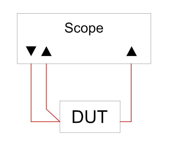
That is a perfectly valid Lab setup where the DUT is the limiting factor and viewed in a vacuum.
Two notes:
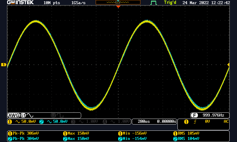
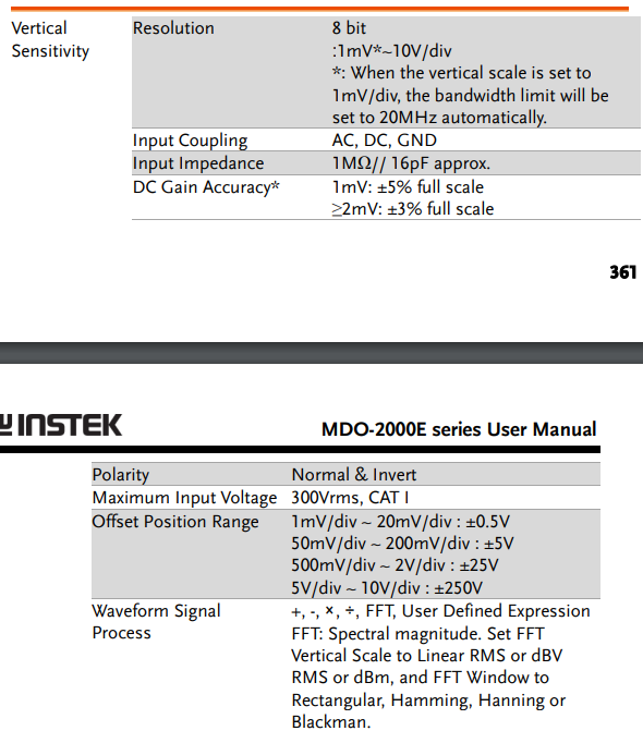
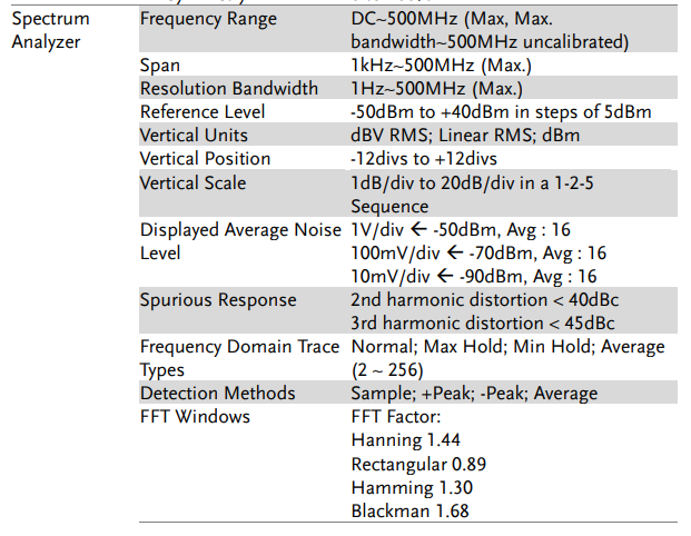
- My scope is running an 8-bit ADC (at stupid high sampling rate), but still only 8-bit. GWInstek is doing some magical fuckery in Spectrum Analyzer mode (definitely not just normal FFT).
- “In a Vacuum” is great! It makes your DUT look stunningly perfect when it has perfect controlled conditions where pass/fail can be picked at ones desire. Or even worse “Look at our arbitrary number!” they exclaim, “It is bigger than out competitors arbitrary number!”
The Goal
I would like an adapter box to make setting up a headphone amplifier to test easier.
Requirements: Whishlist:
-
3x BNC for Signal in, Signal Sense and Signal out
-
pair of RCA-Out for DUT
-
Option to load the DUT via 6.3mm Jack (= Headphone connection)
-
Option to load DUT with “ideal” resistor (= Internal resistors, either fixed “common” values (32, 120, 300, 600) or pick&choose resistor ladder)
-
Shielding/Earthing
-
[Optional] Internal Inductances to approximate some headphones
Point 1) and 2) are just ease of use. I am lazy and since I will use this thing a lot to test DIY projects, I want this adapter to be as Plug&Play as possible.
Point 3) is to prevent the “in a Vacuum”-problem mentioned above. Surely, it is nice to validate output voltage swing into an open circuit to ensure not capacitive issues along the signal path. For me, it would be nice to see how amps fight against whatever weirdness a headphones voice coils present to them.
Point 4) is to explore output power into various loads with more detail than “750mW into 32Ω, 100mW into 300Ω, thanky bye”.
Point 5 
Point 5 is entirely because everyone is doing this wireless bullshit at all frequencies creating this wonderful noise floor that limits what I can measure outside of carefully constructed shield arrangements to ±50mV. Tieing my to-be-constructed adapter in a metal enclosure to ground (via binding post and test lead) should keep that BS out of my measurements!
Point 6 is feature-creep. I want this thing to be as compact as it can be reasonably made to be.
Inspiration
This idea is heavily inspired by this here thread on SBAF:
While the “Do Measurements matter?”-discussion is nice and all, I don’t care about that
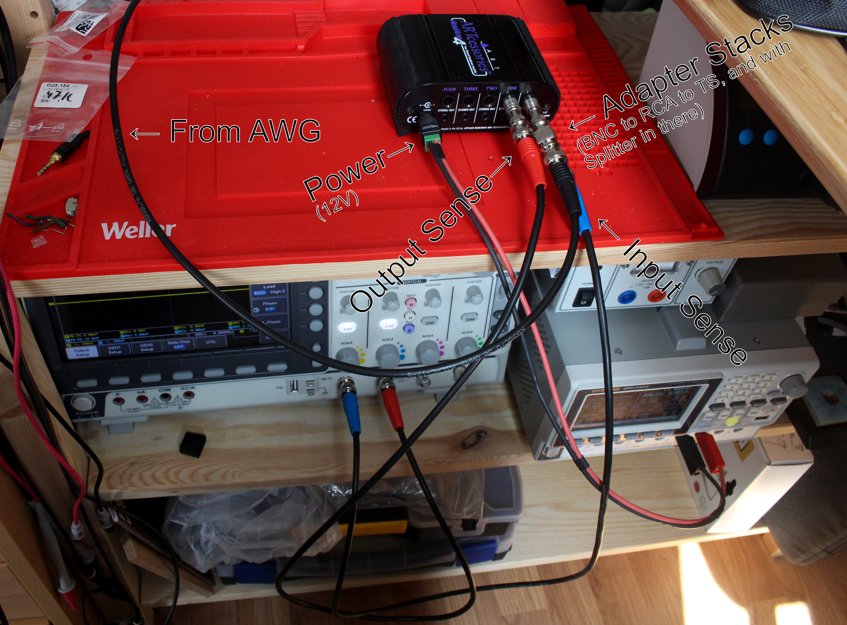
What I do care about is my own frustration. Because I need five or six cables with various adapters and splitters to set up this test that takes at most a minute to run. The flying spaghetti monster sitting on and near my desk when I set this up, is not pretty and quick to yank my DUT off said Desk.
Expect results some time in Q1/22
So, any questions or ideas?