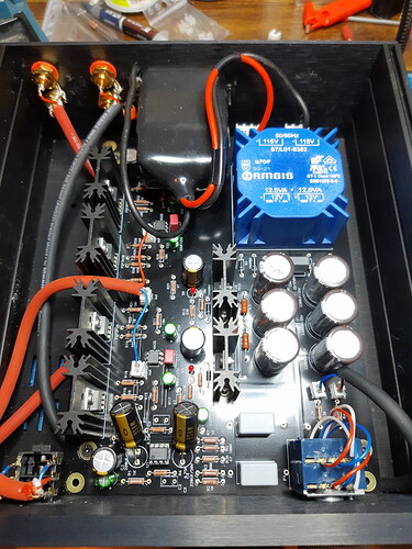
Intro
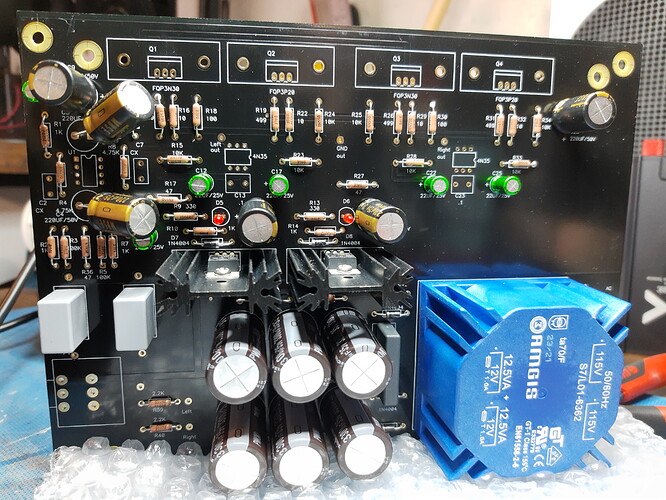
This is my build log for construction of the Whammy headphone amp, an open source, diy amplifier. For those who need it, here is the origin of the amp.
While one could go about it several ways the easiest source for a PCB is the diyAudio Store. There are even more ways you could go about building, modifying or otherwise mounting or casing the amp. I chose to go with the diyAudio Store chassis. I like how it looks and it takes out a significant amount of work that I don’t really have the tools,space or skills for.
The bill of materials is a little less well documented but the most comprehensive I found was here and while this thread on diyaudio.com does include a build guide it is not the one I am following. Instead I will be following this more up to date guide:
Step 1: Components
The first stage was gathering the components. Due to the current global shortages of electronics components some of these proved challenging. In particular mosfets and octocouplers are getting very scarce. For the vast majority of components I used Mouser, for the mosfets and transformer I used Digikey and the octocoupler I found on a tiny Dutch raspberry pi project webshop. The rectifier diodes I found on Audiophonics.
For the vast majority of parts I stuck to the recommended items. The only changes I made were to choose only Nichicon capacitors. All the resistors are Vishay. I’ve also chosen to go with an opamp socket to allow me to swap that out as I prefer. Finally i went with a different power coupler. The standards and requirements in the EU mean that different products apply and I had to take this in to account. In the end I went with the same brand but with medical grade power filtering built in and a removable cartridge mounted fuse.
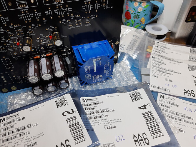
Having gathered all my parts, which were conveniently all delivered in baggies with labels, I added the part numbers from the BOM to each bag so that populating the board would be as straight forward as possible. This also allowed me to check I had all parts and to visually inspect them for defects.
Step 2
PCB Part 1
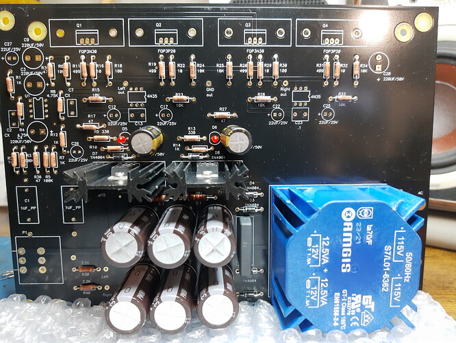
Following the guide, the first step is to populate the power supply section.
Components inserted prior to soldering. On the labels in blue pen is visible the component numbers I added from the circuit diagram
Next these components are soldered to the board. Once done I can then test this for faults before continuing the build.
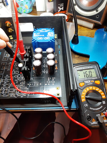
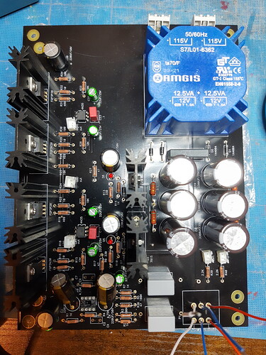
Testing the negative rail
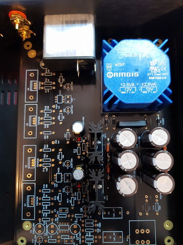
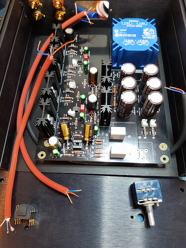
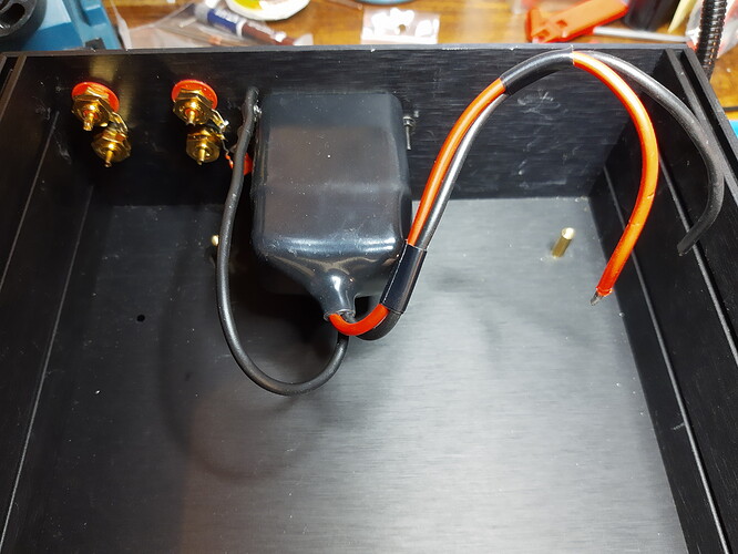
At this point I decided to mock up the power coupling position as it was bothering me. I realised that the way the base panel of this chassis was aligned meant that the coupler and the transformer on the pcb would collide. I turned the base panel upside down so the stand off positions were better. Given that the panels have counter sinks for screw heads there is a clear side preference so this was pretty odd. Easily solved however. Now the board will fit into the chassis.
Next time I post I will be covering populating the rest of the components and mounting/wiring in the chassis.

