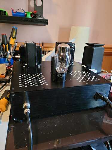
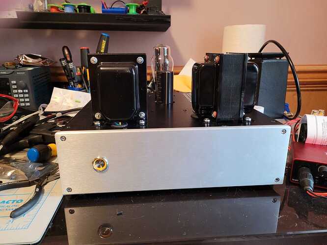
Tube amps are fundamentally simple devices.
When I was planning it I came across the Loftin White design, and was enamored with the direct coupling (no coupling caps). I started with a variant of that design, I modified it to make the load line a bit more friendly for headphone loads.
SRPP was also something that I was enamored with at the time, I copied a design, because at the time I didn’t really understand it well, I have a better grasp now.
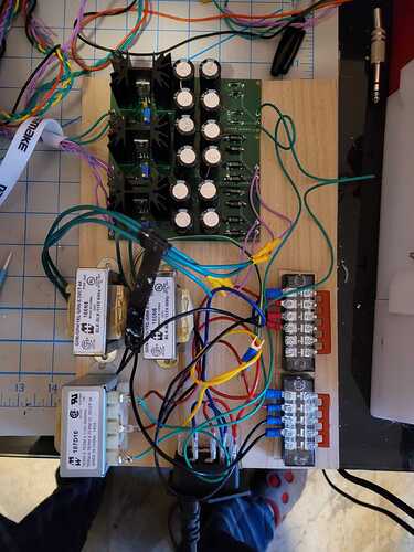
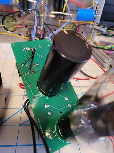
PSU is entirely my fault, I went SS Rectified and regulated, in part because I intended to reuse it, and in part because I wasn’t 100% certain my calculations for load were good enough to hit 400V without the regulator. When I first purchased the parts I misremembered the current requirement, and as a result I have 2 independent PSU’s (1 per channel).
It’s a learning exercise, My intent was to start with AC heaters, swap to DC heaters, so I could evaluate whether the extra complexity was worth it. Try removing the Bypass caps, which in effect adds a degree of local feedback. Start with a transformer designed for speakers and swap to a transformer designed for headphone loads (it’s still sitting in a box while I work through minimizing the noise).
Understand better the difficulties of physical layout.
Things I’ve learned so far
The issue with the Loftin white design, is partly cost, running a higher B+ (400 vs 250) makes everything more expensive, but you also need to lift the cathode on the Power tube by 150V, that’s a lot of resistor and they can carry significant current in the case of a tube failure.
The issue with the SRPP is because the upper triode has it’s cathode lifted to 1/2 B+, you have to be careful not to exceed the maximum Cathode to Heater voltage for the tube, in practice that requires me to lift it’s heater by 50V, so both 1/2’s of the tube are in spec. The way I chose to do that complicates them sharing a heater supply, again adding cost.
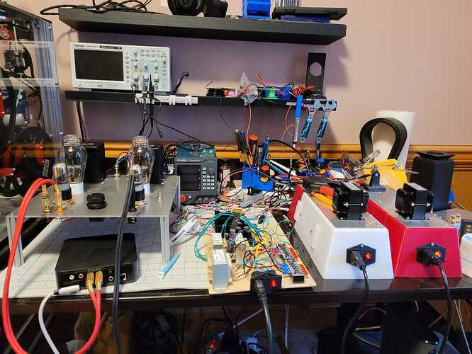
Point to point wiring is painful, and managing grounds in any design requires careful thought.
Neither of those first two things make them bad choices, removing the coupling capacitor removes a source of phase shift in the amp.
The SRPP is a push pull circuit with low output impedance. Though I’m not really exploiting the latter aspect given it’s driving a tube stage with probably >>1 Meg Ohm input impedance.
The amp sounds really good, to the point I need to plug it into a real DAC.
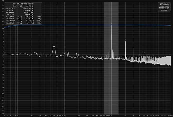
This week I should have enough bits and pieces to actually measure it, it’ll be interesting to compare that to the simulations.
I were building another DHT amp, I’d probably go capacitively coupled, with a CCS on the anode of the input triode. But mostly to see what the difference ends up being.
I’d probably have a few circuit boards made up for it, the cost isn’t a significant portion of the build, and it’s way easier to solder a board with a dozen parts on it than it is to wire those same dozen parts point to point.
I have a Hybrid design I’ve been playing with Triode into SE Mosfet output, that I might build next though.
